Page 1 of 1
6DN7

Posted:
Thu Sep 20, 2012 8:47 pmby xecluded
Greetings,
I just received my clementine board and this time I am thinking about using 6DN7 output tubes as I've heard that 6DN7 has similar sonic character as 45. Would be great if i can get some instruction on how to do this. Thanks.
xecluded
Posted:
Fri Sep 21, 2012 5:32 amby Shannon Parks
Are you planning to cut and jumper V2 & V3 or flying-wire two chassis sockets?
Also, would you start with the Darling circuit I presume? With the Darling circuit you can bias like the diyparadise circuit:
http://diyparadise.com/web/projectsto-k ... dn7-se-amp
I would just leave the Section 1 triode pins unconnected.
Shannon
Posted:
Fri Sep 21, 2012 7:50 amby xecluded
I don't really know where to start. So to begin, I would just put in the parts for the darling circuit.
Can you please explain in layman term (step by step) what you mean by "cut and jumper V2 & V3 or flying-wire two chassis sockets" (i will do which ever easier for me to go back and forth between 6Dn7 and 1626) also what it means to leave section 1 triode pin unconnected.
Many thanks Shane.
xecluded
Posted:
Fri Sep 21, 2012 1:45 pmby Ty_Bower
Cut & jumper is a little tricky, but not too bad. Converting back to VT-137 would be rather difficult, so I'd consider this a permanent change. Flying wire would involve soldering wires into the V2 and V3 holes on the board, and using chassis mount sockets off to the side. You could easily re-arrange the leads to the socket to accomodate whichever tube type you prefer.
Cut & jumper instructions:
1) On the upper side of the board (marked "PUT SOCKET ON THIS SIDE"), cut the trace at V2 leading to pin 3. Cut the trace at V3 leading to pin 2. You might use a sharp hobby knife (X-acto) to cut the traces, or try using the cutoff wheel in a rotary (Dremel) tool. You want to cut the trace near the socket pin, but don't damage the through-hole plating.
2) Flip the board over to the underside of the board. Cut the following traces:
- at V3 leading to pin 3
- at V3 leading to pin 5
- at V3 leading to pin 8
- at V2 leading to pin 2
- at V2 leading to pin 5
- at V2 leading to pin 8
3) As you stuff the board, you will need to install eight jumper wires (insulated solid copper, 18 or 20 gauge). I would install all the jumpers on the underside of the board. Leave enough tail when you cut the excess leads off the resistors so that you can make an easy connection to the jumper wire. It might not hurt to make a little hook or loop before you connect the jumper. The socket holes should be large enough to fit both the pins from the tube socket and the end of the jumper wire, so no worries there.
Jumpers for V3
- from the "3" end of R13 to pin 1
- from the "R" end of R15 to pin 2
- from the "R" end of R17 to pin 3
- from the "R" end of R25 to pin 8
Jumpers for V2
- from the "4" end of R14 to pin 1
- from the "R" end of R16 to pin 2
- from the "R" end of R20 to pin 3
- from the through board via located between R18 and R20, to pin 8
Check my work before you start cutting and jumping. I probably made a mistake somewhere.
Posted:
Fri Sep 21, 2012 2:06 pmby xecluded
wow, so nice of you to spend the time heping me with this. i greatly appreciate your help very much.

Posted:
Fri Sep 21, 2012 2:16 pmby Ty_Bower
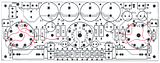
No problem. Here's a picture, in case my written description doesn't make sense. Don't forget the two cuts on the top side of the board.
Posted:
Fri Sep 21, 2012 2:54 pmby EWBrown
I f you're going to do etch cutting and jumpering surgery, then another possibility exists, use parallel connected 6BL7As for V2 and V3.
For the 6DN7 power stages in V2 and V3, the driver V1 should be a 6SN7, as the 6DN7 VA driver section is very close to a 6SN7 (gain of 20, rp of 9000 ohms, gm of 2.2 mA/V) . The power section has a sound which is said to be like that from a a 45, but has higher mu, about 15.4X, and an RP of approx 2000 ohms. OPT primary should be 6K to 8K ohms.
6DN7 output triode is happy with about 325VDC B+, 620 ohm RK and 27 mA cathode current, (for approx 17VDC on the cathode) and don't exceed 30 mA.
If you really want to go out on a limb, try 6CK4s for V2 and V3, with 325V B+, 620 ohm RK, @45 mA cathode current, (28VDC on the cathode) and 4-5 K OPT.
The possibilities are nearly endless....
/ed B
Posted:
Fri Sep 21, 2012 4:31 pmby Ty_Bower
Thinking about it a little more, it's probably best not to cut the board traces of you want to convert from one tube type to the other. Just build out the board per the stock schematic, and add wires to the underside of the sockets. Run the wires to an additional set of chassis mount sockets, adapting the pinout as required. You'll end up with an amp with two sets of tube sockets. Use either the board mounted sockets for 1626, or use the chassis mount sockets for 6DN7. Just don't try to use both at the same time!
As Ed points out, you'll need different cathode resistors for each type, due to their differing dissipation capabilities.
Posted:
Sat Sep 22, 2012 3:49 amby xecluded
Great. That picture sure is worth thousand words

I will just make it as a dedicate board for the 6dn7. Can always buy more boards later on... Thanks again for the great info! I've learn a lot.
