Page 1 of 1

5 pin pc mount sockets?

PostPosted: Sun Sep 25, 2011 1:08 pm
by apurcell22
Hello all,
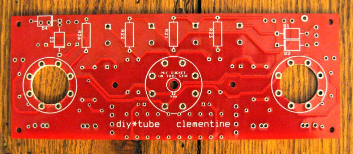
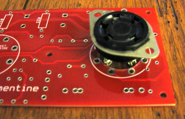
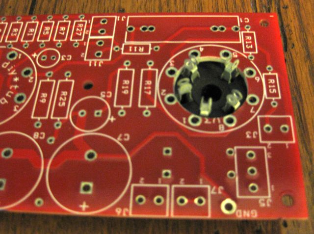
I am going to build an 807 version of the clementine. Have James output transformers, and an Edcor ST-35 clone pt on the way. Does anyone make pc mount sockets for the 807? What is the ma rating for the choke? I have some Radiodaze chokes on hand. Will that work?
Thanks,
Al

PostPosted: Sun Sep 25, 2011 3:37 pm
by TomMcNally
The 5 pin sockets would need to be mounted on the chassis and
wires jumped over. As small as the Clementine board is, it won't
take up much more chassis space. You'll obviously need to
run a plate cap lead with appropriate grommet through the chassis.

The Dynaco style C354 chokes were rated at 200 ma, I think the
Radio Daze are 100. Probably work fine, you won't draw more than
80 ma or so. I've used them in a bunch of amps, usually one per
channel, but that won't be necessary withe the Clementine.

I used the Edcor PWR005 on my "Chubby Clementine" read the
controversial "Spark Test" on how to get the correct phasing.
(hint: my method takes less than one second, no meter required)

... tom

PostPosted: Sun Sep 25, 2011 5:02 pm
by Shannon Parks
With the UX5 sockets, I would suggest the old style chassis mount phenolic. You can mount these directly behind the PCB edge and run jumper wires to the PCB. My buddy Thermion is doing this with 1625s.

But the chassis mount UX5 (not the football shaped ceramics, though) also permit an undocumented feature on the Clementine. You can drill out the center of V2 and V3 up to the inside of the pads and then a UX5 will drop right in for short jumpers to the pads. I may need to drill a board and post the pic.

Shannon

PostPosted: Sun Sep 25, 2011 5:21 pm
by apurcell22
Thanks for the responses. That's a pretty slick trick Shannon. I am a sucker for toobs with plate caps! Can't wait to build this one.
Al

PostPosted: Sun Sep 25, 2011 5:35 pm
by apurcell22
I think that should work great with Pete Millett's big red board to.

PostPosted: Sun Sep 25, 2011 6:03 pm
by Shannon Parks
A 45 degree mounting would line up UX5 pin 2 (the screen with high voltage) by the octal pins 3 & 4 and away from the other low voltage pads. With half inch standoffs, it looks to fit nicely. Could be some issues I'm missing, though. You'd have to pull the whole board if you needed to tighten up a mounting nut for example.

Shannon

Image
Image
Image

PostPosted: Sun Sep 25, 2011 6:16 pm
by apurcell22
Looks good. I'm going to post your suggestion in Pete's thread. With credit going to you of course.
Al

PostPosted: Sun Sep 25, 2011 10:35 pm
by EWBrown
NMow, that's a REALLY creative and original mod (y) (y) (y) :)) O:)

I'd SWAG that this should also work with a UX-7 socket, as they are the same diameter. Maybe even locktal sockets if one wants to go that route with 7C5s or 14C5s (the 6V6GT & 12V6GT equivalents) - that would be more difficult with the center tube socket, too many etches which shouldn't be cut, so no 7F7s or 14F7s, sorry 'bout that, Chief.... :'( .

With the drilled out boards and UX-5 sockets, you might want to use a 1K resistor as the "jumper" for the control grid, keeps the grid stopper closer to the socket, that way.

The other "hack" that I had thought of was to wire-jumper to 9 pin sockets, for all three tubes, and then use a 12AX7 or 12AT7 / 12DT8 driver and two 12B4A outputs, and otherwise exactly duplicate the 1626 circuitry and voltages. That would deliver about 1.5W vs 0.75 for the 1626s.

I've already proven out this concept in a P2P wired 12AT7/12DT8 & 12B4A SET earlier in the year.

Now a REALLY cool rev B Clementine II board could have the two outer sockets set up for both octal and 9 pinners, as with the VA stage in the "Ike" second rev board. *)

/ed B

PostPosted: Mon Sep 26, 2011 4:42 am
by Geek
Gall durn it, ah seen me a commercial build like that and be durned if ah kin remembers who :'(

PostPosted: Mon Sep 26, 2011 5:48 am
by Shannon Parks
I was thinking primarily of the UX5 socket and 807s when I laid out the PCB. But I did manage to find two Amphenol UX7 sockets at the recent hamfest, and while they are fatter I am surprised to find they fit, too. Unfortunately, the extra pins seem to crowd the pads right at the edge. Maybe if I drilled the pads partially away there would be more room (i.e. no shorting) - I think I have a 7/8" hole right now. Probably I will just mount these UX7 behind the PCB and mount a rectifier directly behind the 12SL7.

Nice idea on the screen resistor jumper, Ed. You could connect the other end of the 100 ohm resistor to the pad at R15/R16 near the connector and connect your plate connection to J3-2/J4-2. No HV on any of the pads that way.

Just an FYI that you can't drill out V1 as there are a lot of traces there.

Shannon

PostPosted: Mon Sep 26, 2011 10:01 am
by EWBrown
Maybe, if you were to orient the UX-7 sockets so that the socket's plate pin and the plate pad on the PC board were adjacent, that would take care of any high voltage issues, then jumper the other pins as needed, with a 1K G1 grid stopper and a 100 ohm G2 to plate connection. ( and jumper out the existing G1 stopper R13 and R14, and G2 R15 an R16 resistor locations on the board).

You could probably open the hole up to 15/16" before it got to "biting" into the octal pads too deeply.

/ed B