Page 1 of 2
Clementine 6L6G with 5U4/5R4 Thread

Posted:
Thu Sep 08, 2011 6:51 amby Shannon Parks
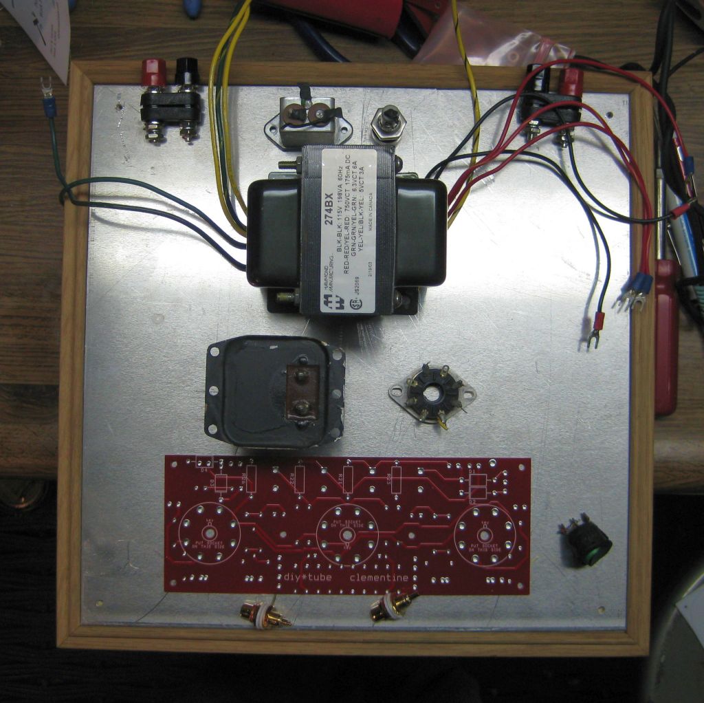
I've stuffed a Clementine board and am waiting on my Edcor shipment, which should arrive in the next week or two. The lead time on the Edcors allowed my brain to think a little too much, and I found a Hammond 274BX lying around. A 650VCT to 700VCT transformer is much more suitable - I just happened to have one of these and I'll really have to lop off some B+ to get closer to 400V. I'll have to mind the input cap voltage rating, too. Anyhow, Ned Carlson sent me this chassis to demo many years ago. It has a .100" thick aluminum lid, a plexiglass bottom and a teflon backing board for interconnects that I think I won't use (worry about rigidity). I found a suitable choke in the junkbox - I think it is >10H. Anyhow, looking for layout ideas. It just isn't clicking on this one.
Main question: where would you put the RCA connectors?
Shannon
Posted:
Thu Sep 08, 2011 8:25 amby katabatic
RCA's on the right, balanced by power switch on the left?

Posted:
Mon Sep 12, 2011 6:47 amby Shannon Parks
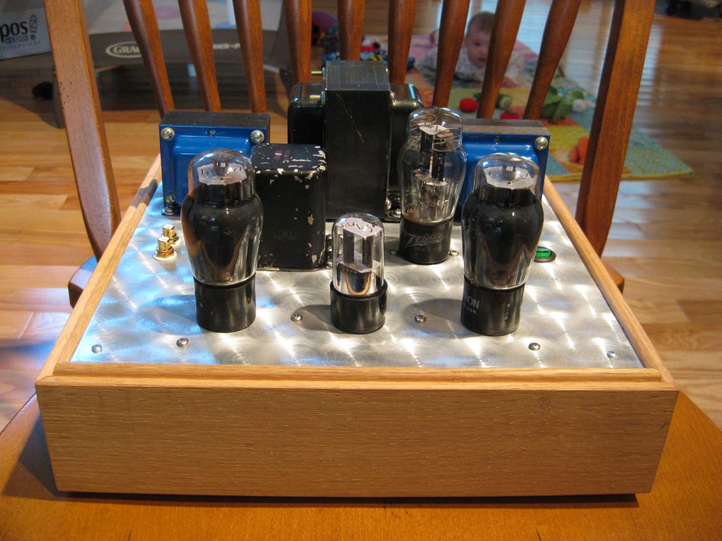
Yes, went with the mirror of the power switch. Backtracked from using the delrin backing panel because I hate any hint of flimsiness when connecting an amp up. Finished all the machine work this weekend. I still need to stain (red mahogany - have tons of it) and seal the wood frame. I also plan to strip the choke to bare metal, fill in the Stancor logo with a black crayon and then seal. Ideas on stripping the paint off of this would be greatly appreciated.
I noticed a neat swirl pattern when I tried deburring with a wire wheel on the drill press. Didn't deburr, but I used it for the swirl pattern and just did it in a few minutes by eye. I think it turned out OK for a first time experiment. I'll leave the aluminum unsealed and will clean with alcohol when needed.
Shannon
Posted:
Mon Sep 12, 2011 8:43 amby TerrySmith
Nice! That's called "engine turned finish" When I was a kid my parents had a '64 Impala SS and the interior metal had a similar finish, really cool.
Posted:
Mon Sep 12, 2011 3:38 pmby dougm216
Nice ! Had it fired yet? Sound?
Posted:
Mon Sep 12, 2011 5:58 pmby DeathRex
I see someone already has lots of hair.
Posted:
Tue Sep 13, 2011 4:30 amby Shannon Parks
dougm216 wrote:Nice ! Had it fired yet? Sound?
Not yet. Hopefully I'll get the cosmetics done today and tomorrow and then bias it up.
DeathRex wrote:I see someone already has lots of hair.
Just in the last week it has really come in all fuzzy! She must be getting ready for winter.
Shannon
Posted:
Wed Sep 14, 2011 11:36 amby Shannon Parks
I was thinking I had a 700VCT 273BX when I ran the initial B+ calcs (this is just a tranny I had on hand). Looks like I will use an coke bottle 5U4 or a potato masher 5R4 to get the B+ as close to 400V as possible. Fiddling with cosmetics this week so I haven't powered it up yet.
Shannon
Posted:
Wed Sep 14, 2011 6:53 pmby 20to20
That really is a sweet look. Nice "experiment". There are a few names for that along with, turning, jeweling...
I found a site that describes how to do that and it gave a warning about using a common steel brush on aluminum saying that bits of the brush will become embedded and rust, that only a stainless steel brush should be used on aluminum.
Posted:
Wed Sep 14, 2011 8:23 pmby Shannon Parks
20to20 wrote:I found a site that describes how to do that and it gave a warning about using a common steel brush on aluminum saying that bits of the brush will become embedded and rust, that only a stainless steel brush should be used on aluminum.
My father-in-law is a bit of a hobby machinist and he told me the same thing (after I did it, of course!). I think I'm going to get a smaller stainless steel brush and redo this on the other side. I'm experimenting with a yellow chromate finish, too. I'd use clear, but my boss has a huge bucket of yellow chromate and the dip tanks. It may turn out sharp, or it may end up splotchy. We'll see.

Shannon
Posted:
Mon Sep 19, 2011 6:35 amby Shannon Parks
Project News:
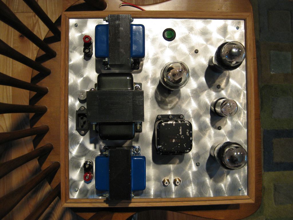
- I stripped the Hammond end bells and the Stancor choke with acetone. I felt like I needed more uniformity with the iron complement, so I also prepped the Edcor output bells with a green scratchy and then wiped down with acetone. All these were then painted with Hammertone black. Looked sharp, and I'll post pics.
- My ST-shaped 6L6GAs have pin 1 populated on their socket and they needed to be strapped on the PCB. I put wire jumpers between pin 1 and pin 8 on the PCB at V2 and V3. I was worried that if I had put this in the layout I might have an unintentional problem with 1626s, but I probably should have just done it. Note that this mod needs to be done for other tubes like EL34s and KT88s, too.
- My Stancor choke was dodgy, with an intermittent open. This caused very large voltage spikes as it acted like a large voltage booster. It took out one of the caps.
- I replaced the Stancor with a C354 and changed all my power supply caps. I changed the input cap to a 16uF, 600V chassis mount.
- Unfortunately, I'm still not getting the voltage drop I want. These tube rectifiers heat up so fast that I can have B+ soaring much higher at turn on than I'd like (>500V). This transformer - a 274BX - just won't work.
- Instead of getting a lower VCT tranny, I'll just revert back to the originally spec'd PA774 clone from Edcor and scuttle the tube rectifier. C'est la vie. At least I can now run my 1625s.
Shannon
Posted:
Mon Sep 19, 2011 8:39 amby miker
You can try changing the first cap to 1.0 or 0.68 uF. It will act more like a choke input power supply and drop more voltage. You can model it in PSUD to see the effect. It's easy enough to try. What voltage are you trying to get to?
Posted:
Tue Sep 20, 2011 5:08 amby Shannon Parks
miker wrote:You can try changing the first cap to 1.0 or 0.68 uF. It will act more like a choke input power supply and drop more voltage. You can model it in PSUD to see the effect. It's easy enough to try. What voltage are you trying to get to?
I've done this trick before, but unfortunately the voltage will still soar high before any load current is drawn (note: I could use a 5AR4 at that point, but don't want to - too many fixes). Shooting for a B+ of around 400V. I'd much rather have all my power supply caps as modern 450V electrolytics. So ultimately not a big deal, as I just pulled this transformer from the Eiclone test box without thinking. I'll just plop in my new Edcor and maybe order a second Edcor with a 5V so I can spec a tube rectifier build for the Clementine.
Shannon
Posted:
Tue Sep 20, 2011 7:44 amby TerrySmith
Try a 50 or 100 ohm resistor between the rectifier tube and the board, leaving the board stock, that should get the voltages in the ballpark. You may have to go back to a 5V4 or 5AR4 rectifier.
This seems to work out perfect when I use AA-100 transformers with EL84 tubes
Posted:
Tue Sep 20, 2011 8:53 amby DeathRex
If you have a extra 6V filament supply you can put that on your 5R4 with a CL60-70 in series. The CL will greatly slow down the turnon time for the 5R4. Alternatively you can try a CL-150 or 110 with a slighly high 5V filament (5.3-5.6) in series to slow down a 5R4. The CL-150 will drop about 0.67 volts at 2 amps, and 0.61 volts at 3 amps when warmed up.