I fitted the new flared ports Saturday morning and wired up the crossovers, plopping in the drivers. JT came over and we broke them in with the new Bonnie Raitt album. Sounded pretty nice and they looked fantastic. But after he left, I set up my test gear and saw some flaws.
There was a nice notch at around 3kHz about 10dB down in the frequency response. I tested the second speaker and saw the exact same response. Huh - what did I do wrong? I went back and re-examined my crossover calculations, and some slop I had in them to account for a rising peak around the crossover frequency was definitely the issue. I had used some Kentucky windage there (i.e. the tweeter had a slightly higher crossover frequency than the woofer), but that SWAG was probably only useful with a 1st order filter. Once I switched to a 2nd order Linkwitz-Riley, the crossover frequency needed to be the same. I realize this seems elementary, but original thinking was a 1st order filter and me having L1 external as I unwrapped wraps until it was perfect. I had changed the game, but stayed with the old game plan. I went ahead and re-ran the numbers with the online calculator:
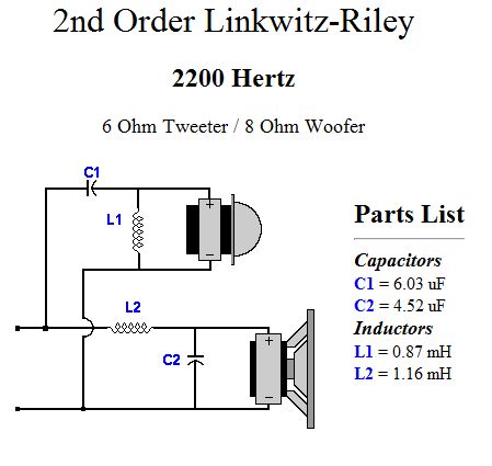
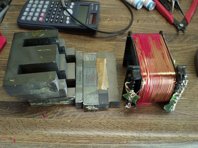
I decided to leave L2 and C2 alone. I have L2 nailed, and my C2 was 5uF but high quality. My C1 was 5uF (the two series 10uF Spragues), so I needed another 1uF. I used a nice fat green 1uF Russkie cap that Ed Brown sent me years ago. Perfect! Now I needed my inductor - a 600uH ferrite bobbin that I had salvaged from the SM82 crossover - to be 870uH. What to do? Obviously, an order to Parts Express is not in order for the DIYer. I didn't have any magnet wire so I took this power supply out of my junkbox, which was from a broken Aiwa setero my boss had thrown out. It looked to be an E core, with one side of lams welded on. So I guessed I might be able to break the weld with a few strikes from a hammer.
I soldered the salvaged 19 AWG magnet wire to the outside lead of the 600uH inductor and just started wrapping.
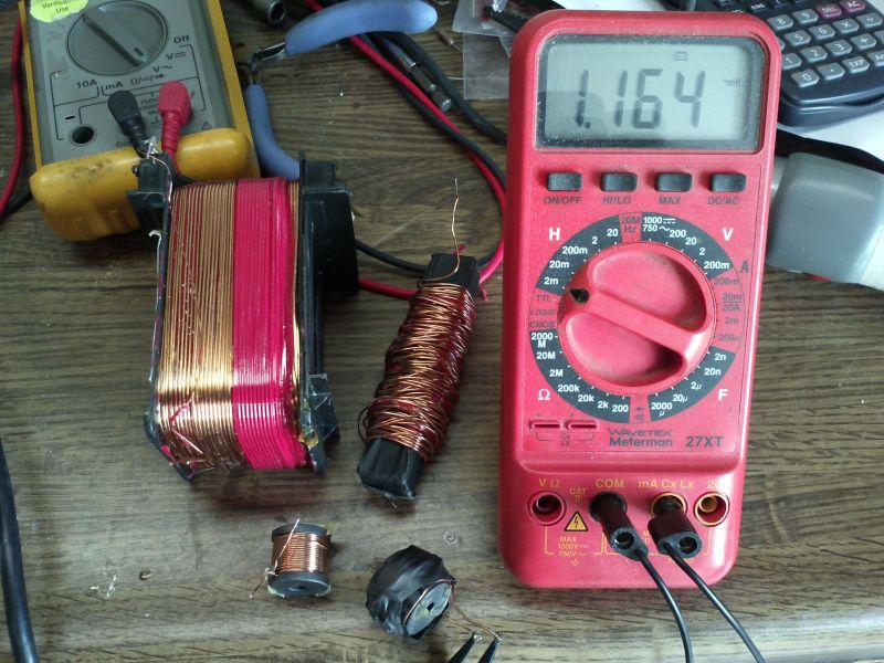
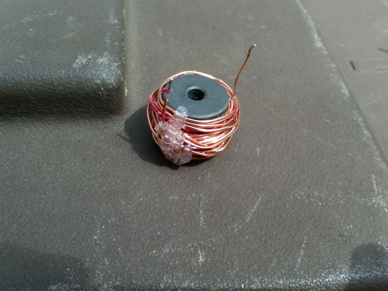
Ultimately, I unwrapped my extra wraps back to 870uH exactly. I made my changes to the high pass, sealed it up and tested away.
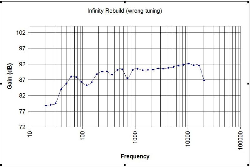
Looking good! I have those same resonances from earlier due to my driveway. I think some of the frequency rise is due to my imperfect test gear (i.e. a cheap digital RS SPL meter). Lastly, this shot is *before* I tuned my bass port. The impedance test on this speaker showed I had it tuned at 35Hz (1.85" dia, 5.5" long, uncut flared port), and the recommendation from Parts Express (and my own WinISD Beta calc) was 45Hz. I'll report on how I did that later, and hopefully more SPL shots showing a tightened up bass region. Oh - and pictures of the speakers!
Shannon