The BEST way to build a GSG for headphones only?

2nd harmonics for the masses

Postby highflyin9 » Wed Jul 11, 2012 1:10 pm

haha, most audiophiles do turn their nose up at tone controls. I found a really basic passive bass control here: http://www.sentex.ca/~mec1995/tutorial/ ... xtor5.html

Image

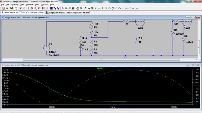
The loudness boost, if I'm not mistaken, attenuates out most of the midrange but leaves the bass and treble, so it may not be ideal in my particular situation.
My DIY Electronics Blog: DIYAudioBlog.com
User avatar
highflyin9
 
Posts: 119
Joined: Tue Jul 27, 2010 7:42 pm
Location: East Coast

Postby highflyin9 » Wed Jul 11, 2012 4:49 pm

separks wrote:So we want a 7.64:1 turns ratio. About the closest we come is the GXSE10-16-1.7K (or the GXSE15). That would be 10.3:1. It would behave as a 6.4k:60 ohm transformer. The reflected load would be a touch more linear and lost max output would be minimal. A volume control on the input would still be advisable for max level control.


Would the Transcendar TT-023-OT also work? It has 16ohm taps and looks very close. Specs: 1.6K with 40% Ultra Linear tap to 4, 8, &16 ohms, Frequency Response: 20 Hz to 100 kHz, Maximum DC Bias Current: 160 mA, Primary DC Resistance: 86 ohm
My DIY Electronics Blog: DIYAudioBlog.com
User avatar
highflyin9
 
Posts: 119
Joined: Tue Jul 27, 2010 7:42 pm
Location: East Coast

Postby Shannon Parks » Wed Jul 11, 2012 7:29 pm

As far as a KISS bass boost, you'd grab a 100k ALPS pot with the loudness terminal (the mysterious fourth terminal). You'd hang something like 50k and .033uF cap from there to ground. You'd get +3dB at 20Hz and about 1dB at 150Hz. The cap could be adjusted per one's taste. I may experiment with the new Budgie SE amp using this technique. A treble boost cap (like in the following link) can be left off. Here's a good write up:
http://www.robkalmeijer.nl/techniek/ele ... index.html

That Transcendar looks fine. The neat thing about the multiple taps means you can also experiment with the headphone having a resistive load in parallel (like a 5W 50 resistor). This helps average out any crazy impedance changes apart from the amplifier's own damping factor (per my earlier 20/20 post).

Shannon
User avatar
Shannon Parks
Site Admin
 
Posts: 3764
Joined: Tue Mar 18, 2003 5:40 pm
Location: Poulsbo, Washington

Postby Shannon Parks » Thu Jul 12, 2012 6:17 am

Here's a few simulations using LTSpice with a treble boost added, too. Note that I am using four resistors to simulate the loudness pot. The boost RC is always at the 50k-50k center point. I assume this is the way the Alps are - I ordered a couple this morning. Anyhow, I can still manipulate the wiper with this method. The lower half of the pot rotation will always have the same EQ, while the effect of the EQ lessens on the upper half. Since this is still a log pot, we will usually be in the lower half. But when we are in the upper half, we can assume louder music that suffers less from the perceived loudness phenomenon. So it all is kind of ingenious. You could use two DPDT switches:one as a Treble boost switch and one as a Bass boost. I find I almost always use a couple dB boost on my bass, and selectively engage a slight boost or go flat at >10kHz.

Shannon

Image

Image

Image
User avatar
Shannon Parks
Site Admin
 
Posts: 3764
Joined: Tue Mar 18, 2003 5:40 pm
Location: Poulsbo, Washington

Postby highflyin9 » Thu Jul 12, 2012 8:33 am

Lots of good information here! Thanks for your insight Shannon.
My DIY Electronics Blog: DIYAudioBlog.com
User avatar
highflyin9
 
Posts: 119
Joined: Tue Jul 27, 2010 7:42 pm
Location: East Coast

Postby MidSentry54 » Thu Jul 12, 2012 10:00 pm

So So Sooooo happy to see all this info! Thanks for your input Shannon! My search for a proper transformer begins now. ;)
MidSentry54
 
Posts: 7
Joined: Sun Jul 08, 2012 9:09 pm

Postby MidSentry54 » Thu Jul 12, 2012 10:27 pm

highflyin9 wrote:Hello 20, If this is being built as a headphone amplifier then there will be a potentiometer / attenuator in the unit and no preamp. Signal would be coming straight from a CD player.


That reminds me of another question I had- anyone know what the input impedance and sensitivity is on a GSG? I'm tailoring the output stage of my B3 DAC to suit.
MidSentry54
 
Posts: 7
Joined: Sun Jul 08, 2012 9:09 pm

Postby MidSentry54 » Thu Jul 12, 2012 10:39 pm

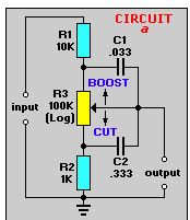
separks wrote:As far as a KISS bass boost, you'd grab a 100k ALPS pot with the loudness terminal (the mysterious fourth terminal). You'd hang something like 50k and .033uF cap from there to ground. You'd get +3dB at 20Hz and about 1dB at 150Hz. The cap could be adjusted per one's taste....

Shannon


Yes! Or, as an alternative to something a bit more high end, the various capacitance values could be selected via rotary switching (like a nice grayhill)- leaving at least one selection setting to make the whole circuit defeatable.
MidSentry54
 
Posts: 7
Joined: Sun Jul 08, 2012 9:09 pm

Postby highflyin9 » Tue Jul 17, 2012 3:40 pm

Still brainstorming on this idea. Since I've seen multiple headphone amplifiers with OTs run into magnetic flux issues, I've been trying to figure out a chassis configuration that would work well and keep the OTs as far away from the PA774 as possible. Then I realized that toroids have a much less issue with magnetic interaction and I thought using one for the power might be more ideal than splitting hairs trying to keep the xformers away from each other.

Are either of these a suitable replacement for the PA774? They're a little overrated but the specs seem to be the closest.

Antec AS-2T300
http://www.antekinc.com/details.php?p=730

Antec AS-2T350
http://www.antekinc.com/details.php?p=731
My DIY Electronics Blog: DIYAudioBlog.com
User avatar
highflyin9
 
Posts: 119
Joined: Tue Jul 27, 2010 7:42 pm
Location: East Coast

Postby Shannon Parks » Thu Jul 19, 2012 5:23 am

The Antek AS-2T300 and the smaller AS-1T300 look fine. The secondary taps would be series connected and used as the center tap.

I did flux testing on a set of Edcors just recently, as things will be tight on my Budgie SE amp (6"x10"x2"). I monitored the loaded output transformers and looked for any noise as I shifted my transformers around. My results:

1) Power transformer to output transformer coupling: The outputs had zero extra noise at 1.5" to 2" away from the power transformer regardless of the lam alignments (i.e. 0 degrees, 90 degrees, etc.). The power amp's noise floor was around 200uV.
2) Output transformer to output transformer coupling: For the output testing, I had one with a 3.5W output (max amp output) and one with none. The only flux issues I had were when the lams were less than .050" away. And it wasn't very much either. But if the lams touched, the noise really jumped. I could fix 95% of that with a piece of electrical tape and then I could butt them together (for testing sake). Crosstalk wasn't a problem - not sure if it was good naturally or if I shorted the grid of the power tube in the test channel.

Shannon
User avatar
Shannon Parks
Site Admin
 
Posts: 3764
Joined: Tue Mar 18, 2003 5:40 pm
Location: Poulsbo, Washington

Postby highflyin9 » Thu Jul 19, 2012 1:41 pm

Thanks for the info Shannon! My most notable experience with flux interaction was the Millett Jonokuchi project. Here's my build here:

Image

While the hum isn't bad, it's notable with headphones. These are relatively small Edcor transformers too. I thought the choke might of had something to do with it but it's the power transformer in the vicinity of the outputs, which is surprising considering the distance between them.

It's this project that's made me so leery of the situation, but I think with care, everything will be just fine. I'm going to proceed with the Antek AS-2T300 and steel shell.
My DIY Electronics Blog: DIYAudioBlog.com
User avatar
highflyin9
 
Posts: 119
Joined: Tue Jul 27, 2010 7:42 pm
Location: East Coast

Postby Shannon Parks » Fri Jul 20, 2012 5:00 am

So in your Jonokuchi is the power supply stock, but the choke replaced R5? Or are there other mods?

Shannon
User avatar
Shannon Parks
Site Admin
 
Posts: 3764
Joined: Tue Mar 18, 2003 5:40 pm
Location: Poulsbo, Washington

Postby highflyin9 » Thu Aug 16, 2012 12:32 pm

Thanks for all the info you emailed me about the Jonokuchi Shannon. Right now I'm amassing the parts necessary for the GSG headphone amp. I have another quick question as I lay out the chassis. Using that handy transformer turns calculator, the 16 ohm taps on the Transcendar TT-023-OT are ideal for the Audeze being 50 ohms (An 8.367 turn ratio which is close enough to a 10 turns ratio). Based on the same calculator, if I use the 4 ohm taps, they would be a 20 turn ratio, which is very close to the turns ratio on 3.5k/8ohm (20.917). So my assumption is that I could use the 4 ohm outputs for 8 ohm speaker taps on the same amp, allowing it to do double duty for speakers / headphones. Is this a correct assumption?
My DIY Electronics Blog: DIYAudioBlog.com
User avatar
highflyin9
 
Posts: 119
Joined: Tue Jul 27, 2010 7:42 pm
Location: East Coast

Postby Shannon Parks » Thu Aug 16, 2012 3:19 pm

You are correct about the 4 ohm tap.

Higher efficiency headphones would have made the whole design easier and one could just use the standard output transformer impedance for loudspeakers and add the 20/20 circuit. They just don't need the voltage drive like the Audeze does. I've been listening to my Budgie SE all week at work with my Sony MDR-V6 headphones, and I've been extremely happy with the performance. Noise is a tiny 180uV and about 110uV A weighted.

BTW, all my spice above was done with a linear pot, and the 50% taps are at around 12K for a 100K pot. I plan to post the updated sims later - email me if anyone needs the values.

Shannon
User avatar
Shannon Parks
Site Admin
 
Posts: 3764
Joined: Tue Mar 18, 2003 5:40 pm
Location: Poulsbo, Washington

Previous

Return to get*set*go

Who is online

Users browsing this forum: No registered users and 7 guests

cron