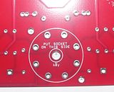
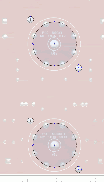
Maybe I'm just being too picky. If I punch the chassis hole a little bigger than the socket, it doesn't matter a whit. I can also bolt the board to the chassis before I solder the socket down, and wiggle it a little until it lines up perfectly. I was curious when I plopped the board down on my drawing, and most everything lined up perfectly except the bottom socket hole. As I said, it isn't off by much.

I haven't looked at the fpd file, as I haven't installed their software kit.

I haven't looked at the fpd file, as I haven't installed their software kit.
