Chassis layout - OOP?
17 posts
• Page 1 of 2 • 1, 2
Chassis layout - OOP?
Every photo I've ever seen of a Get*Set*Go seems to have the transformers arranged output - power - output. Has anyone built one arranged some other way? Where's the layout with all the output transformers on one side, and the power tranny tucked off to the corner?
"It's a different experience; the noise occlusion, crisp, clear sound, and defined powerful bass. Strong bass does not corrupt the higher frequencies, giving a very different overall feel of the sound, one that is, in my opinion, quite unique."
-
Ty_Bower - KT88
- Posts: 1494
- Joined: Wed Mar 21, 2007 2:50 pm
- Location: Newark, DE
You could edit the G*S*G FrontPanelExpress files with the FPE software. Piece of cake!
- designer of fine tube audio gear at (((parks audio)))
- founder and admin of the diytube forums
-

Shannon Parks - Site Admin
- Posts: 3764
- Joined: Tue Mar 18, 2003 5:40 pm
- Location: Poulsbo, Washington
The O P O seems more logical that the O O P or P O O since
the circuit board is symmetrical and with the power transformer in
the middle and the outputs on either side, everything is in
a straight line from input to output with short leads.
Anything works - go for it !
the circuit board is symmetrical and with the power transformer in
the middle and the outputs on either side, everything is in
a straight line from input to output with short leads.
Anything works - go for it !
Last edited by TomMcNally on Tue Apr 21, 2009 7:49 pm, edited 1 time in total.
-

TomMcNally - Darling du Jour
- Posts: 2729
- Joined: Sat Nov 19, 2005 2:19 pm
- Location: Northfield, NJ
Sure... but I want to see how it turned out for someone else! I don't want to be the prototype!
"It's a different experience; the noise occlusion, crisp, clear sound, and defined powerful bass. Strong bass does not corrupt the higher frequencies, giving a very different overall feel of the sound, one that is, in my opinion, quite unique."
-

Ty_Bower - KT88
- Posts: 1494
- Joined: Wed Mar 21, 2007 2:50 pm
- Location: Newark, DE
For a "cheapskate" version, using the Edcor XSE or GXSE OPTs, they could be mounted under the chassis, which would simplify the construction (less drilling and punching), though it would lose the "cool"
OPO look.
I generally go with the "symmetrical" look, though I have donw "OOP" or "POO" as well


/ed B
OPO look.
I generally go with the "symmetrical" look, though I have donw "OOP" or "POO" as well


/ed B
Real Radios Glow in the Dark
-

EWBrown - Insulator & Iron Magnate
- Posts: 6389
- Joined: Wed Mar 19, 2003 6:03 am
- Location: Now located in Clay County, NC !
EWBrown wrote:For a "cheapskate" version, using the Edcor XSE or GXSE OPTs, they could be mounted under the chassis, which would simplify the construction (less drilling and punching), though it would lose the "cool"
OPO look.
Hey! I resemble that remark!
I've ordered all the transformers from Edcor - XPWR005 for the power, and GXSE15 for the outputs. I'm very tempted to stick the outputs under the chassis. I'm planning to leave enough room up top so I can upgrade them someday. I've got a pair of Transcendar 5K:8 which I could "borrow" from another amp. I like those Magnequest RH60 (with the end bells) that you put on yours, too. Of course, I suppose if I mounted the GXSE underneath and then later went to the regular RH60, I could keep them underneath too.
I'm not worried about drilling or punching holes, but I would rather not have a piece of swiss cheese when all is said and done. I wish I had some kind of universal output transformer mounting system...
"It's a different experience; the noise occlusion, crisp, clear sound, and defined powerful bass. Strong bass does not corrupt the higher frequencies, giving a very different overall feel of the sound, one that is, in my opinion, quite unique."
-

Ty_Bower - KT88
- Posts: 1494
- Joined: Wed Mar 21, 2007 2:50 pm
- Location: Newark, DE
Eventually I am going to build up a "test bed" version of the GSG, and use the octal relay sockets for the power tubes, which would make all sorts of tube-rolling an easy job. Just perfect for trying out 6CK4s, 6AV5GAs, 6BQ5GTBs, parallaled 6BL7s, etc.
The basic goal is to keep the power supply and the 6SL7 driver sections close to "normal", and then experiment with the output sections.
I won't bother with CCS or any "fancy circuit tricks" here... Otherwise it would just become an example of comparing apples to durian fruit
I figure that cheapo-OPTs would be best suited for this project, and I also have a couple of the old spugly "tar baby" dipped Dynaco PA774 power tranniess harvested from some old beat up ST35 carcii, that work well but look truly, scarey-ugly.
That must have been their first early attempt at silencing "buzzy" power trannies.
This will become a functional, though not beautiful, "ugly duckling" though not exactly a "Quakti" either

/ed B
The basic goal is to keep the power supply and the 6SL7 driver sections close to "normal", and then experiment with the output sections.
I won't bother with CCS or any "fancy circuit tricks" here... Otherwise it would just become an example of comparing apples to durian fruit

I figure that cheapo-OPTs would be best suited for this project, and I also have a couple of the old spugly "tar baby" dipped Dynaco PA774 power tranniess harvested from some old beat up ST35 carcii, that work well but look truly, scarey-ugly.

That must have been their first early attempt at silencing "buzzy" power trannies.
This will become a functional, though not beautiful, "ugly duckling" though not exactly a "Quakti" either


/ed B
Real Radios Glow in the Dark
-

EWBrown - Insulator & Iron Magnate
- Posts: 6389
- Joined: Wed Mar 19, 2003 6:03 am
- Location: Now located in Clay County, NC !
Okay, so I guess I'll forget about the OOP and POO concepts for now.
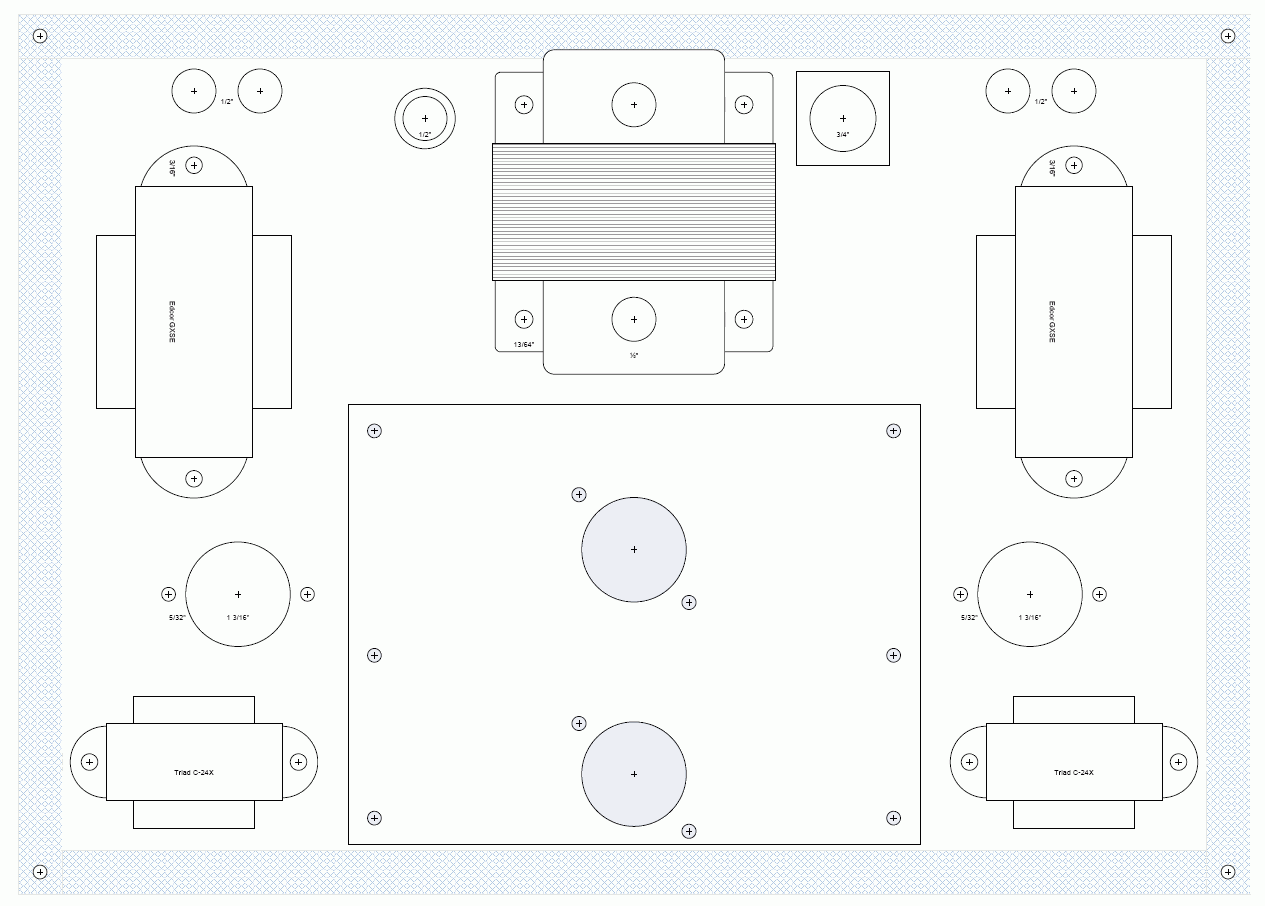
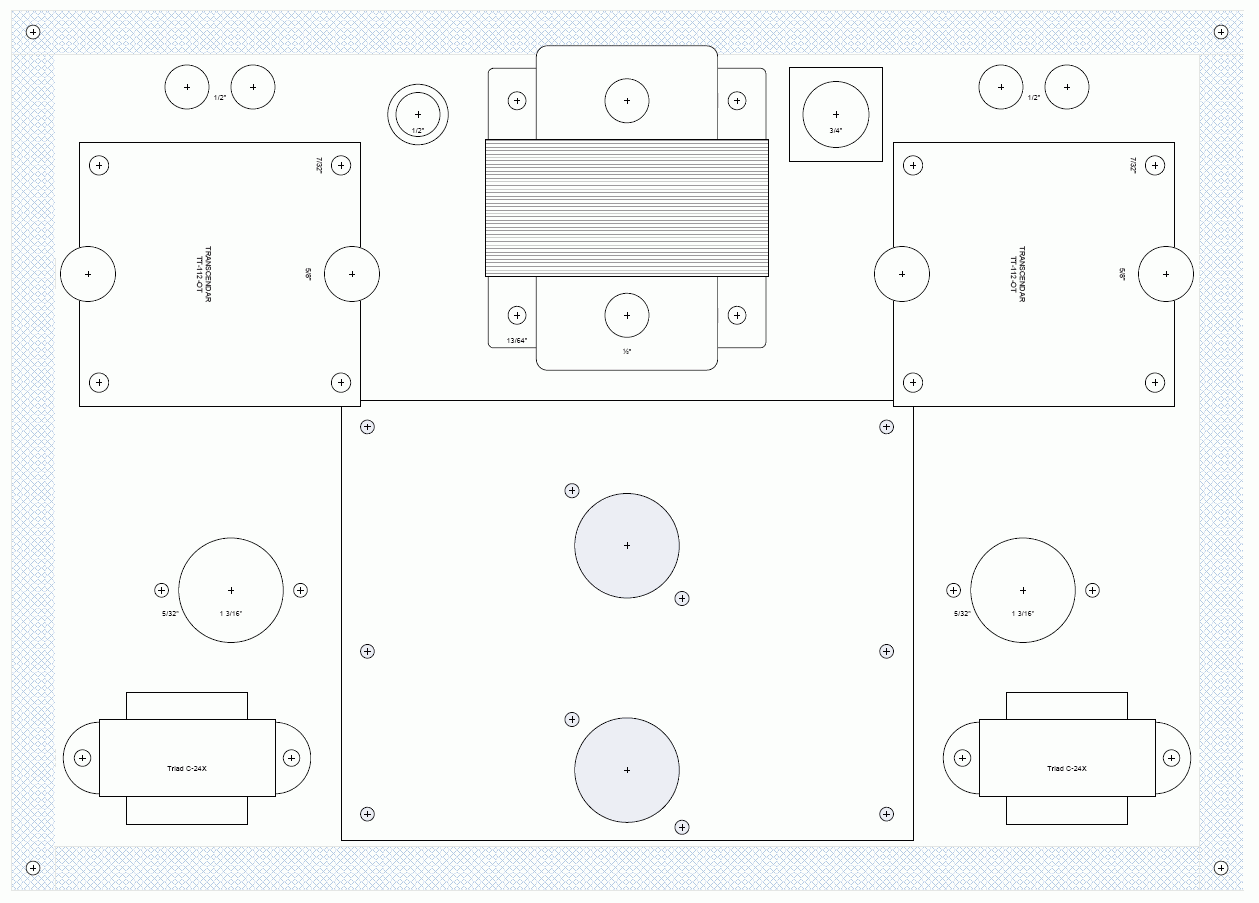
I've got a piece of aluminum for the chassis plate, 14" x 10". Here's my ideas for fitting the Edcor power and GXSE output transformers. I think the Magnequest RH-60 (open frame) are the same size as the GXSE, so they could potentially be drop-in upgrades. There's also room to squeeze on a pair of Transcendar up top if desired. Everything fits on the plate, except the IEC connector for the power cord (it'll go on the back) and the RCA input jacks (they'll probably go on the front). I've bought a second 1H choke to use in place of R17a/b. I think Ed did the same thing on his.
Any comments before I start drilling?
Just kidding about the drilling part... I haven't even stuffed the board yet.
I've got a piece of aluminum for the chassis plate, 14" x 10". Here's my ideas for fitting the Edcor power and GXSE output transformers. I think the Magnequest RH-60 (open frame) are the same size as the GXSE, so they could potentially be drop-in upgrades. There's also room to squeeze on a pair of Transcendar up top if desired. Everything fits on the plate, except the IEC connector for the power cord (it'll go on the back) and the RCA input jacks (they'll probably go on the front). I've bought a second 1H choke to use in place of R17a/b. I think Ed did the same thing on his.
Any comments before I start drilling?


Just kidding about the drilling part... I haven't even stuffed the board yet.
"It's a different experience; the noise occlusion, crisp, clear sound, and defined powerful bass. Strong bass does not corrupt the higher frequencies, giving a very different overall feel of the sound, one that is, in my opinion, quite unique."
-

Ty_Bower - KT88
- Posts: 1494
- Joined: Wed Mar 21, 2007 2:50 pm
- Location: Newark, DE
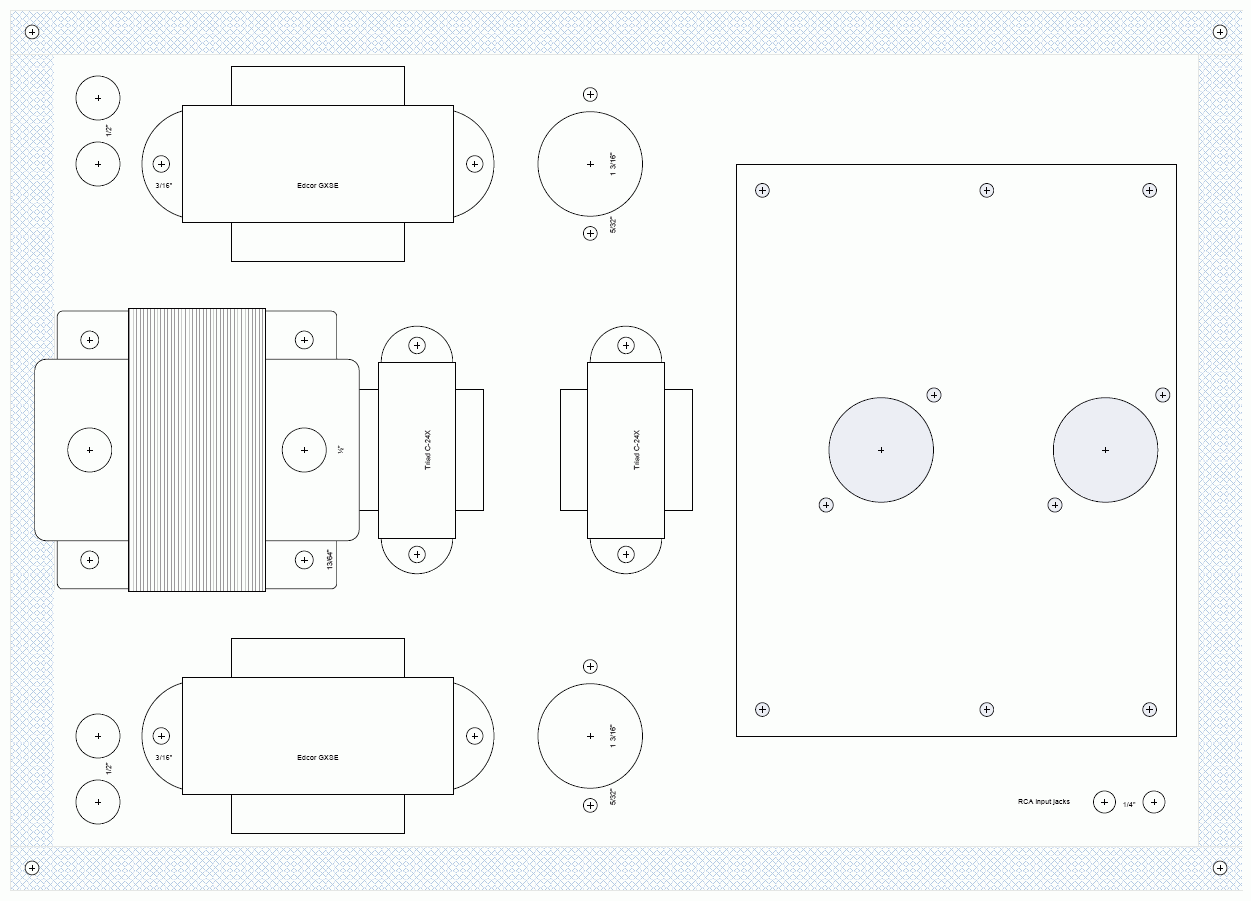
After seeing Tom's latest G*S*G, I decided to try a similar layout. I think this works better, except I won't be able to fit the Transcendar OT. Oh well. The spacing between the Triad chokes is such that I can rotate the whole mess 90 degrees (on the random chance it somehow benefits me to do so). I just need to find a spot to stick the fuse and the power switch. Oh, and I need Edcor to ship me the transformers, too.

"It's a different experience; the noise occlusion, crisp, clear sound, and defined powerful bass. Strong bass does not corrupt the higher frequencies, giving a very different overall feel of the sound, one that is, in my opinion, quite unique."
-

Ty_Bower - KT88
- Posts: 1494
- Joined: Wed Mar 21, 2007 2:50 pm
- Location: Newark, DE
That looks good - I wish I had rotated my power transformer 90 degrees so the wires would have been long enough without extending them.
Are you going to mount the Edcor outputs underneath ?
I do it for a couple of reasons ...
1) they are ugly
2) high voltage is exposed
3) easier - less holes to drill
Are you going to mount the Edcor outputs underneath ?
I do it for a couple of reasons ...
1) they are ugly
2) high voltage is exposed
3) easier - less holes to drill
-

TomMcNally - Darling du Jour
- Posts: 2729
- Joined: Sat Nov 19, 2005 2:19 pm
- Location: Northfield, NJ
Yes, all the open frame iron goes underneath, along with the circuit board. The only (big) things sticking out the top will be the Edcor power transformer and four tubes. I think I'm going to put the IEC, fuse, and power switch all on the back.
I actually don't mind drilling holes. I've got a little drill press stand, and it goes through aluminum real quick. The slow part is deciding where to put the holes. I spend way too much time sketching out the chassis in Visio. I suppose it gives me something to do while waiting for the transformers to be wound...
Tom - do you have any idea how much DC the little Edcors will tolerate? They don't specify anywhere on their web site. If it makes any difference, I ordered the GXSE15 instead of the XSE.
"It's a different experience; the noise occlusion, crisp, clear sound, and defined powerful bass. Strong bass does not corrupt the higher frequencies, giving a very different overall feel of the sound, one that is, in my opinion, quite unique."
-

Ty_Bower - KT88
- Posts: 1494
- Joined: Wed Mar 21, 2007 2:50 pm
- Location: Newark, DE
I searched around on Edcor's site also, they don't seem to have
the specs listed for max voltage or current on transformers.
I'm sure you will be well within spec with a 6B4G amp though.
I have a tabletop drill press, but I don't use it for amps.
The best method I've found is to use an Automatic Center Punch
and ping the hole in the the white China marker dot I use when
I line things up. Then drill with a tiny pilot drill, and work my
way up to the size needed, I used Greenlee chassis punches
for 1/2" holes for binding posts and fuseholders, and the
appropriate larger size for tube sockets. The holes are clean
and precise that way. I use a (genuine) UniBit for odd size
holes like the .625" holes for the Heyco grommets and the
power switches. I use a Dremel tool with a fiberglass cutting
wheel to make the IEC power jack hole, after marking it
with grease pencil. I can doing them in about 60 seconds
with no filing required.
I like a symmetrical or at least balanced look when possible.
-

TomMcNally - Darling du Jour
- Posts: 2729
- Joined: Sat Nov 19, 2005 2:19 pm
- Location: Northfield, NJ
Another chassis question - I printed out the .dxf files (from the docs and mods thread), but I noticed the socket holes don't line up perfectly. If you print them out and set the unpopulated board over top, the bottom hole is off by a good 1/32". You can also see they are off if you use the measure tool in Autodesk Design Review. In the drawing, the center of the socket hole is not on the line formed by the centers of the two adjacent mounting holes. If you check the board, you can see that it should be.
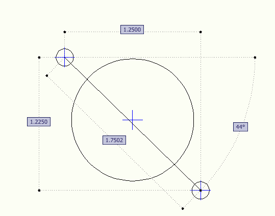
Does anyone have the precise measurements for the centers of the ten mounting holes and the two socket holes?

Does anyone have the precise measurements for the centers of the ten mounting holes and the two socket holes?
"It's a different experience; the noise occlusion, crisp, clear sound, and defined powerful bass. Strong bass does not corrupt the higher frequencies, giving a very different overall feel of the sound, one that is, in my opinion, quite unique."
-

Ty_Bower - KT88
- Posts: 1494
- Joined: Wed Mar 21, 2007 2:50 pm
- Location: Newark, DE
Ummm .... I've built five get*set*go amps ... and I haven't
seen the need for those holes to line up with the tube socket.
They are used to hold the board to the top plate with spacers.
The board uses PC mount sockets, like the ones I sent you.
The sockets you bought weren't the intent of the design.
Did you bring up the top plate designs we used in
Front Panel Designer ? That might be helpful.
Sorry I can't be of more help ... I build my amps with
a Makita battery powered drill and Greenlee chassis punches
and a UniBit.
-

TomMcNally - Darling du Jour
- Posts: 2729
- Joined: Sat Nov 19, 2005 2:19 pm
- Location: Northfield, NJ
17 posts
• Page 1 of 2 • 1, 2
Who is online
Users browsing this forum: No registered users and 9 guests

