I am pleased.
Thanks to Shannon and all the DIY Tubers!

![]() by hembrook » Thu Jan 31, 2008 12:34 am
by hembrook » Thu Jan 31, 2008 12:34 am
![]() by Shannon Parks » Thu Jan 31, 2008 6:06 am
by Shannon Parks » Thu Jan 31, 2008 6:06 am

![]() by hembrook » Thu Jan 31, 2008 12:04 pm
by hembrook » Thu Jan 31, 2008 12:04 pm
![]() by hembrook » Thu Feb 07, 2008 3:19 pm
by hembrook » Thu Feb 07, 2008 3:19 pm
![]() by Shannon Parks » Fri Feb 08, 2008 7:02 am
by Shannon Parks » Fri Feb 08, 2008 7:02 am
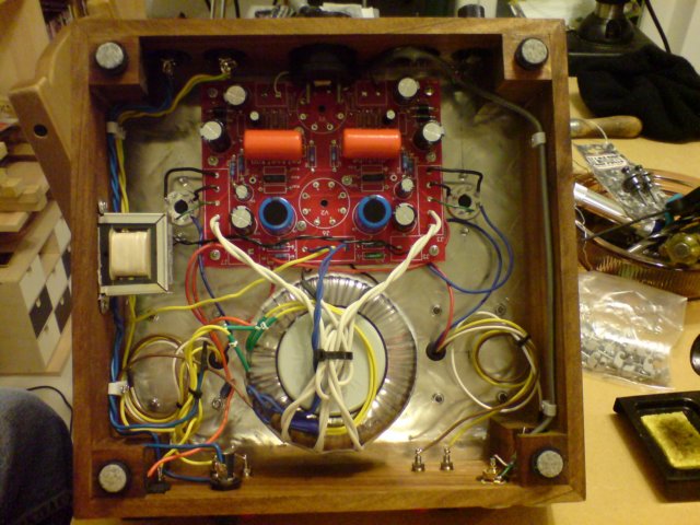
hembrook wrote:The hum comes from the right speaker. My voltage divider coming off the heater network ties to the left input, which is noticeably quieter. Any suggestions?
Would a variable pot instead of the 51 and 47 ohm resistors make a difference? Or am I thinking the wrong direction here?
![]() by EWBrown » Fri Feb 08, 2008 7:08 am
by EWBrown » Fri Feb 08, 2008 7:08 am

![]() by hembrook » Fri Feb 08, 2008 1:44 pm
by hembrook » Fri Feb 08, 2008 1:44 pm
![]() by Shannon Parks » Sat Feb 09, 2008 8:35 am
by Shannon Parks » Sat Feb 09, 2008 8:35 am
hembrook wrote:The hum comes from the right speaker. My voltage divider coming off the heater network ties to the left input, which is noticeably quieter. Any suggestions?
![]() by hembrook » Sat Feb 09, 2008 8:39 am
by hembrook » Sat Feb 09, 2008 8:39 am
![]() by Shannon Parks » Sat Feb 09, 2008 8:49 am
by Shannon Parks » Sat Feb 09, 2008 8:49 am
![]() by hembrook » Sat Feb 09, 2008 11:53 am
by hembrook » Sat Feb 09, 2008 11:53 am
![]() by Shannon Parks » Sat Feb 09, 2008 11:57 am
by Shannon Parks » Sat Feb 09, 2008 11:57 am
hembrook wrote:Can I tie a 1 ohm resistor from TP1 and TP2 to ground, then measure the voltage drop across this to calculate tube plate (cathode) current?
![]() by hembrook » Sat Feb 09, 2008 5:40 pm
by hembrook » Sat Feb 09, 2008 5:40 pm
separks wrote:hembrook wrote:Can I tie a 1 ohm resistor from TP1 and TP2 to ground, then measure the voltage drop across this to calculate tube plate (cathode) current?
No, since the 1 ohm would be in parallel with the bias resistors. Just divide the voltage at TP1 and TP2 by 900.
![]() by Shannon Parks » Sat Feb 09, 2008 6:15 pm
by Shannon Parks » Sat Feb 09, 2008 6:15 pm
![]() by hembrook » Sun Feb 10, 2008 2:56 am
by hembrook » Sun Feb 10, 2008 2:56 am
Users browsing this forum: No registered users and 19 guests