OK, this is a bit geeky, but I made a provision for a panel meeter in my case. I plan on installing a 100mA ammeter with a switch so I can switch back and forth between the two power tubes to check the idle current. Am I doing something dumb here?
Bigger question: Generally you add the ammeter in series with the cathode resistor on its way to ground, yes? Given that the cathode resistor is also allied with the filament supply (to float the filaments) where do I hook the thing up?
Thanks!
Installing a panel meter
13 posts
• Page 1 of 1
Installing a panel meter
![]() by hembrook » Fri Jan 25, 2008 5:02 pm
by hembrook » Fri Jan 25, 2008 5:02 pm
- hembrook
- Posts: 122
- Joined: Wed Oct 31, 2007 3:36 pm
OK. Unfortunately I already have the Ammeters...
![]() by hembrook » Fri Jan 25, 2008 6:22 pm
by hembrook » Fri Jan 25, 2008 6:22 pm
Also, given that the cathode resistor is actually 3 in parallel... and biased 50 volts.... How do I wire it in?
Thanks for the quick answer!
Thanks for the quick answer!
- hembrook
- Posts: 122
- Joined: Wed Oct 31, 2007 3:36 pm
![]() by Ty_Bower » Fri Jan 25, 2008 7:44 pm
by Ty_Bower » Fri Jan 25, 2008 7:44 pm
I don't have a GSG, so I'm kinda making a swag here. But, it seems that Shannon put a test point (labelled TP) on the circuit board. There is one between R11 and the three R15 resistors. There is a second one between R12 and the three R16 resistors.
I'd bet you a 6p14p that all you need to do it hook your voltmeter across the test point and ground.
Lesse... 15a, 15b, and 15c are 2.7k all in parallel. Together that makes 900 ohms. I'm not familiar with these directly heated triode, but it seems like we want the cathode to be about 50 volts above the grid. Let's pretend you measure 50 volts at the test point. Then using V=IR, V is 50 and R is 900. Therefore the current is 50/900 = 0.055 amps, or 55 milliamps.
Did I get it right?
-

Ty_Bower - KT88
- Posts: 1494
- Joined: Wed Mar 21, 2007 2:50 pm
- Location: Newark, DE
Groovy
![]() by hembrook » Fri Jan 25, 2008 7:52 pm
by hembrook » Fri Jan 25, 2008 7:52 pm
I understand where you are going with this. I had to delve into the Eiclone forum to see what the TP points (Test Points I imagine) are. They are not mentioned in the GSG manual.
This all sounds reasonable. However, I am still left with a 100mA ammeter and circuit design for a voltmeter. Darn.
Thanks for the suggestion.
This all sounds reasonable. However, I am still left with a 100mA ammeter and circuit design for a voltmeter. Darn.
Thanks for the suggestion.
- hembrook
- Posts: 122
- Joined: Wed Oct 31, 2007 3:36 pm
![]() by Ty_Bower » Fri Jan 25, 2008 8:50 pm
by Ty_Bower » Fri Jan 25, 2008 8:50 pm
Well, you could wire the "bottom" of the sets of resistors (R15*, R16*) to the poles of a DPTP switch. Then wire one throw of one pole to the meter, and the other throw of the other pole to the meter. The remaining throws get wired to ground, as does the remaining connection on the meter. Something like this:

Of course, you can't operate the amp without having one or the other channel running through the meter all the time. And, I think you'd damage a tube or a speaker if you were foolish enough to flip the switch while the amp were running. All in all, it's a fantastically poor idea. I think using an ammeter is just about the complete wrong way of doing this.
You can always take a voltmeter and strap a dropping resistor across it to measure current, but I know of no way to use an ammeter to measure voltage. Perhaps one of our cleverer readers has the answer...
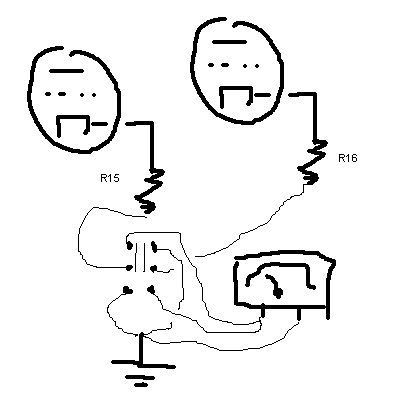
-
Ty_Bower - KT88
- Posts: 1494
- Joined: Wed Mar 21, 2007 2:50 pm
- Location: Newark, DE
I understand that one way to measure current is...
![]() by hembrook » Sat Jan 26, 2008 8:21 pm
by hembrook » Sat Jan 26, 2008 8:21 pm
by a little math after measuring a voltage across a resistor. What you are doing is implying current because you are using a volt meter. I have something that measures current. Why is it seemingly so difficult to leave it in the circuit?
I guess there are multiple ways to skin a cat.
I suppose I could use a volt meter and a 1 ohm resistor... But that kinda defeats the purpose of having bought a ammeter in the first place.
I guess there are multiple ways to skin a cat.
I suppose I could use a volt meter and a 1 ohm resistor... But that kinda defeats the purpose of having bought a ammeter in the first place.
- hembrook
- Posts: 122
- Joined: Wed Oct 31, 2007 3:36 pm
![]() by TomMcNally » Sat Jan 26, 2008 9:28 pm
by TomMcNally » Sat Jan 26, 2008 9:28 pm
There is no reason you can't switch a meter between two
channels using the schematic Ty_Bower drew ... it would
be better to have two meters permanently wired though.
Switching the cathodes hot isn't a good idea.
I used a one ma meter in my 300B amp, and with a
bunch of resistors, which simply sample the points
of interest, I can read total B+, B+ on each tube,
cathode current on each 300B, B+ on each driver, and
cathode current on each driver. The meter happens to
have perfect scales for voltage and current.
-

TomMcNally - Darling du Jour
- Posts: 2729
- Joined: Sat Nov 19, 2005 2:19 pm
- Location: Northfield, NJ
Neato! Got an example of how you wired it up?
![]() by hembrook » Sun Jan 27, 2008 2:49 pm
by hembrook » Sun Jan 27, 2008 2:49 pm
Does switching it on the fly produce any undesirable effects?
- hembrook
- Posts: 122
- Joined: Wed Oct 31, 2007 3:36 pm
![]() by TomMcNally » Sun Jan 27, 2008 3:21 pm
by TomMcNally » Sun Jan 27, 2008 3:21 pm
Try the switch and see how it goes ... use a small toggle
switch, not a switch than could get stuck in the middle,
and you should be ok. Just flip it fast.
switch, not a switch than could get stuck in the middle,
and you should be ok. Just flip it fast.
-
TomMcNally - Darling du Jour
- Posts: 2729
- Joined: Sat Nov 19, 2005 2:19 pm
- Location: Northfield, NJ
Actually I was wondering about the switch
![]() by hembrook » Sun Jan 27, 2008 4:32 pm
by hembrook » Sun Jan 27, 2008 4:32 pm
Since we are talking using a toggle, I was wondering if a center off would have advantages, so I could selectively choose which to use.
Brings to mind the idea of make before break for the ground loop, so that you have, say left tube ground on one setting, make to ground(no effect, then break in the "off" setting, then make before break to ground for the right tube.
Where did you tap into for checking cathode (or plate) current?
Thanks!
- hembrook
- Posts: 122
- Joined: Wed Oct 31, 2007 3:36 pm
![]() by TomMcNally » Sun Jan 27, 2008 8:21 pm
by TomMcNally » Sun Jan 27, 2008 8:21 pm
I don't think there is a way to make a center off switch work.
Maybe a rotary switch ...
Two meters is still the ideal way to do it.
My amp uses a 0-1 ma meter which is basically
a voltmeter ... 750 k resistor = 750 volt scale
It's measuring the voltage across the cathode resistors
with an appropriate value series resistor.
Maybe a rotary switch ...
Two meters is still the ideal way to do it.
My amp uses a 0-1 ma meter which is basically
a voltmeter ... 750 k resistor = 750 volt scale
It's measuring the voltage across the cathode resistors
with an appropriate value series resistor.
-
TomMcNally - Darling du Jour
- Posts: 2729
- Joined: Sat Nov 19, 2005 2:19 pm
- Location: Northfield, NJ
So potentially I could pop open my ammeter and rework it..
![]() by hembrook » Mon Jan 28, 2008 6:12 am
by hembrook » Mon Jan 28, 2008 6:12 am
Just remove the bridge resistor that is inside it and rewire it as a volt meter and use the standard 1 ohm resistor from cathode to ground with the ammeter taps on either side of it?
I presume that my ammeter is simpley a voltmeter (really a galvanometer) with its own resistive bridge inside. Not really rocket science, and the meters are cheap, so I am not afraid to break it.
I presume that my ammeter is simpley a voltmeter (really a galvanometer) with its own resistive bridge inside. Not really rocket science, and the meters are cheap, so I am not afraid to break it.
- hembrook
- Posts: 122
- Joined: Wed Oct 31, 2007 3:36 pm
13 posts
• Page 1 of 1
Who is online
Users browsing this forum: No registered users and 7 guests