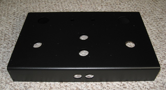
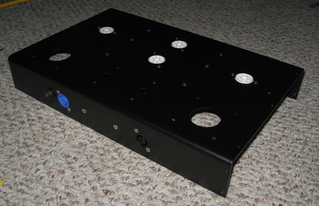
nineno's build journal

2nd harmonics for the masses

nineno's build journal

Postby nineno » Sat Jun 30, 2007 8:28 am

Well, there’s no turning back now: I received my getSETgo board in the mail mid-week along with my PCB octal sockets, my Solen caps, the 6SL7, the 6AX5-GT and some miscellaneous connectors. I even found some time to cut and bend a chassis.

Front 3/4 View:
Image
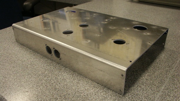
The chassis was cut from 0.130" 3000-series aluminum plate. The flat panel measured 14-3/4" by 16".
After the panel was bent to from the front and rear the chassis measured roughly 2-1/2" tall, 16" wide and 10-1/4" deep.
The two hole patterns on the front of the chassis are for Neutrik RCA input jacks: Neutrik Co. RCA Panel Jack Products Page.
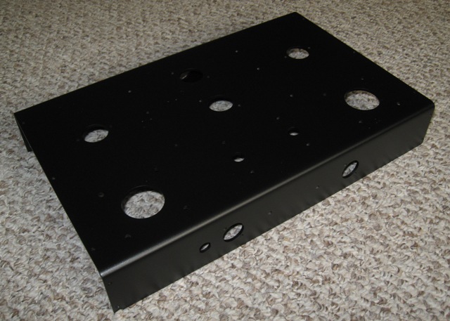
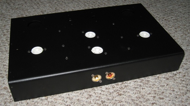
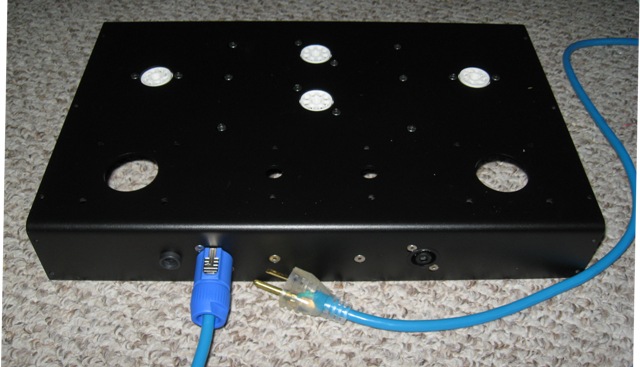

Top 3/4 View:
Image
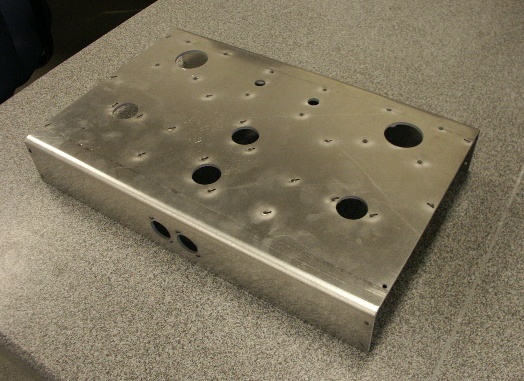
All of the PCB, octal, and jack mounting holes are 0.140" holes for 6-32 fasteners.
The mounting holes for the power transformer are 0.170" for 8-32 fasteners.
I guessed at the stud size of the James OPTs. The hole size is currently 0.20" (5mm). Does anyone recall what the actual stud size for the James OPTs are?
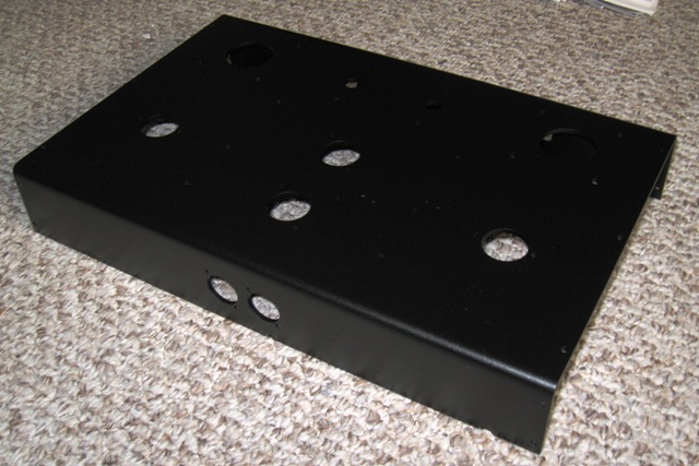
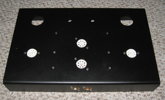
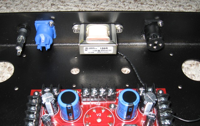

Back 3/4 View:
Image
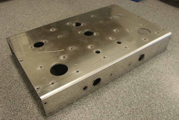
Here on the back panel you can see the double-D cutout for the fuse holder and two more Neutrik jack hole patterns.
These hole patterns are for Neutrik Speakon loud speaker interconnect and PowerCon power interconnect.
The two holes on either size of the chassis centerline (between the two panel jack hole patterns) are for the choke, which should mount on the inside of the chassis, and under the power transformer.
I took a leap of faith on this, and I hope that the orientation (and core flux, etc) of the choke and transformer isn't detrimental to the performance of the amp. Any thoughts on that?


I'll try to add updates with pictures as I move forward. The next steps are:
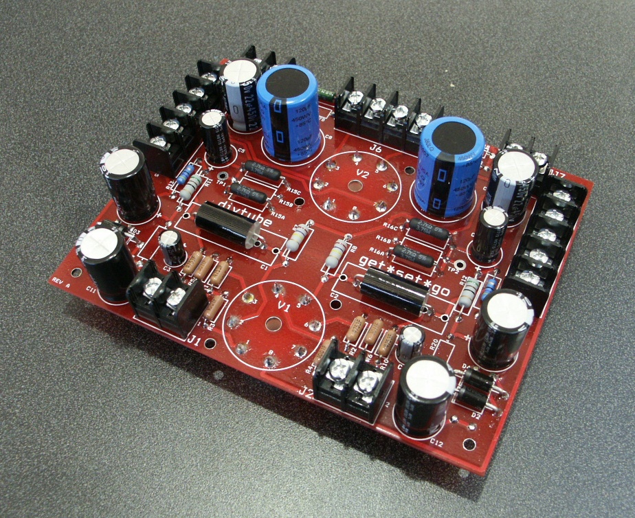
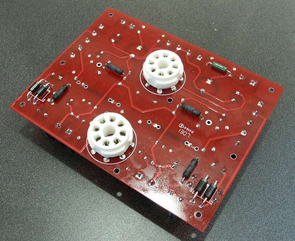
1. Stuff and solder the PCB - I'm using mostly the called for components. I had to sub out a few parts that were back ordered and I picked different electromechanicals (fuse holders, switches, etc)
2. Powdercoat the chassis- I'm still up in the air on what color. I think I want to use the champagne James OPTs, so I need to pick something that looks good with that. Wrinkle black looks good with everything, right?
3. Make decorative wood end-plates. The right side end plate with have the power switch countersunk 2 or 3 inches back from the front plate. Otherwise, the panels will be taller and deeper than the chassis by about 3/32" and 1/2" wide; this will make the amp 17" wide.

Any input, comments or questions are appreciated.
drew*
nineno
 
Posts: 117
Joined: Sat Aug 02, 2003 10:59 pm

Postby WA4SWJ » Sat Jun 30, 2007 8:37 am

nineno,

Now this is going to be interesting. The chassis looks great and I can imagine it all painted up and mounted on some great looking wood end panels. Keep the pictures coming. Wish I had the metal working capability - I'd make one like that too. I'll have a Hammond black chassis on Monday to start on.

Great work and please keep sending in those pics!
Ed Long
User avatar
WA4SWJ
KT88
 
Posts: 650
Joined: Mon Dec 27, 2004 8:39 pm
Location: Belleview, FL

Postby Shannon Parks » Mon Jul 02, 2007 2:25 am

Man, that .130" is a friggin' tank. You oughta paint it mil-spec gray. ;) Nice work!
User avatar
Shannon Parks
Site Admin
 
Posts: 3764
Joined: Tue Mar 18, 2003 5:40 pm
Location: Poulsbo, Washington

Postby nineno » Mon Jul 02, 2007 5:59 am

separks wrote:Man, that .130" is a friggin' tank. You oughta paint it mil-spec gray. ;) Nice work!


Yea, it's a healthy chunk of metal...left-overs from a previous (load bearing) project. Of course, it is 3000-series AL so it's more like metallic Play-Dough than metal.
nineno
 
Posts: 117
Joined: Sat Aug 02, 2003 10:59 pm

Postby mesherm » Mon Jul 02, 2007 9:15 am

Does anyone recall what the actual stud size for the James OPTs are?


I don't have any metric hardware. The 6112s I used had holes instead of studs so I used 6-32 hardware to mount the trannies and it left "wiggle" room. I would SWAG that #8 hardware would be the limit.
User avatar
mesherm
KT88
 
Posts: 1232
Joined: Fri Aug 27, 2004 10:33 pm
Location: Alvin Texas

Postby TerrySmith » Mon Jul 02, 2007 9:32 am

I used 8-32 on mine, the threads hit the sides, but not bad.

BTW, thanks to whoever recommended Bolt Depot for stainless hdwe, it's faster and a lot cheaper then diggin' around Lowes! Yellow_Light_Colorz_PDT_06
T. Smith
User avatar
TerrySmith
KT88
 
Posts: 973
Joined: Sat Jan 31, 2004 12:51 pm
Location: Maryville TN

Postby nineno » Thu Jul 05, 2007 10:12 pm

Unfortunately, there's been relatively little progress this week.

I stuffed and soldered the PCB using the components that were called out in the instruction manual, except for the signal capacitors. I had a pair of Solen caps collecting dust so I put them to use.

The octal sockets were ordered through TubeDepot.com along with the 6SL7GT and the 6AX5GT.

From the bottom...
Image

From the top...
Image

Hopefully I'll have more to report in the near future.
drew*
nineno
 
Posts: 117
Joined: Sat Aug 02, 2003 10:59 pm

Postby nineno » Tue Jul 17, 2007 7:47 pm

Well, I do have more to report, but none of it is good: I busted my knee cap in a slow-speed motorcycle accident a week ago. Instinct took over and proper motorcycle technique was forgotten.

I go under the knife tomorrow but I'm still fighting to get the chassis powder coated this weekend.

More after the drugs wear off...
drew*
nineno
 
Posts: 117
Joined: Sat Aug 02, 2003 10:59 pm

Postby mesherm » Tue Jul 17, 2007 8:24 pm

OUCH Yellow_Light_Colorz_PDT_13
User avatar
mesherm
KT88
 
Posts: 1232
Joined: Fri Aug 27, 2004 10:33 pm
Location: Alvin Texas

Postby wiredbecker » Wed Jul 18, 2007 1:29 am

Sorry to hear it.

On the bright side, it leaves more time to work on your amp? I only say that because, when I broke my wrist skateboarding, not only did soldering boards keep me from going crazy, but it helped speed my recovery.

Good luck healing up quick.
User avatar
wiredbecker
KT88
 
Posts: 301
Joined: Mon Mar 26, 2007 3:48 pm
Location: Albany Landfill, CA

Postby nineno » Tue Aug 14, 2007 4:00 pm

Finally, so minor progress to report: The chassis is powder coated.

Front 3/4 View
Image

Rear 3/4 View
Image

Front & Top
Image

As you can see, the powder coat is a very subtle wrinkle black. Unfortunately, there are a few clumps in the finish, perhaps because of the age of the powder.

Right now the plan is to use the champagne OPTs, but that's always subject to change.

Now it's time to test-fit the components I do have...
nineno
 
Posts: 117
Joined: Sat Aug 02, 2003 10:59 pm

Postby nineno » Thu Aug 16, 2007 7:41 pm

With the chassis back in my hands I've tried to make a bit more progress. At times I've progressed backwards, but things look pretty good so far. There are several more pictures below - Have a look and let me know if you have any questions.

Front 3/4 View:
Image
Here you can see the chassis with the RCA jacks mounted on the front of the chassis and the PCB and 6B4G octal sockets mounted in the chassis.
The fasteners are all 6-32 stainless steel flat head cap screws. Most of the fasteners thread into the 1/2" standoffs for the PCB, but the screws that hold the jacks thread into K-Nuts (nuts with a captured free spinning star washer).


RCA Jacks:
Image
This is a slightly clearer picture of the RCA jacks on the front of the chassis. Red insulation ring for right, white for left. As mentioned in the first posting on this topic, the jacks and connectors are all Neutrik brand. They're not particularly boutique, but they work very well, they're well manufactured and the power and speaker jacks have unique functionality.

Top of Chassis:
Image
Here you can see all of the counter sunk fasteners.


Rear 3/4 View:
Image
The black panel jack to the right is the Neutrik Speakon jack. The blue panel jack is the PowerCon power inlet jack. The speaker jack houses all four contacts for the left and right speaker output. For the power and speaker jack, the plug inserts into this jack and turns about 15-degrees clockwise to lock in place. There is a small trigger on the plug that must be depressed before it can be rotated counter-clockwise to remove the plug from the jack.

Rear Panel with Power Cord:
Image
This picture shows the power cord connected to the PowerCon jack. The small metal release trigger is visible on the top of the blue plug.
The power cord started life as a brand new extension cord but the blue was a near-match for the Neutrik plug so I bought the extension cord and chopped off the first 6-feet. Anyone need a blue cord with an illuminated female Edison plug molded on the end?!
The two fasteners centered in the chassis hold the choke in place on the inside of the chassis. These are 8-32 fasteners.


Rear Panel Jacks from Inside the Chassis:
Image
Here you can see the choke mounting and the termination on the Neutrik jacks. Will this choke orientation present any issues with EMF?

RCA Jacks from Inside the Chassis:
Image
Last but not least, the business-side of the RCA jacks: As you can see, the housings are made from cast aluminum. The shield of the RCA jack is isolated from the housing.
Solder termination for each channel is just an inch and a half from the signal input on the PCB.


Let me know if you have any questions!
nineno
 
Posts: 117
Joined: Sat Aug 02, 2003 10:59 pm

Postby parabellum » Thu Aug 16, 2007 8:08 pm

thats some fancy metal-work
User avatar
parabellum
 
Posts: 195
Joined: Wed Apr 25, 2007 1:37 pm
Location: Bay Area, CA

Postby nineno » Thu Aug 16, 2007 8:30 pm

parabellum wrote:thats some fancy metal-work


Thanks Parabellum. I wish I could take credit for actually working the metal. The chassis was cut on a water jet so all I did was layout the holes in AutoCAD.

The bends were nothing more than a shot on each side in a press break, which required little-more than setting the break depth and stomping on a pedal switch.

The most metal work I've done is counter sinking the holes for the cap screws, which was a little tedious with a hand drill. I messed up two of the holes (drilled to deep) and had to fill them with Devcon aluminum oxide epoxy and re-drill them and touch up the grey epoxy with black paint. That's the "reverse-progress" I mentioned in my last post.

Never the less, thanks much for the kind remarks. Mostly, I'm benefited by having access to machine tools, though. :)

Thanks again...I'll post more when the piggy bank has enough in it to buy the remaining big-ticket items.

drew*
nineno
 
Posts: 117
Joined: Sat Aug 02, 2003 10:59 pm

Postby parabellum » Thu Aug 16, 2007 8:53 pm

nineno wrote:
parabellum wrote:thats some fancy metal-work


Thanks Parabellum. I wish I could take credit for actually working the metal. The chassis was cut on a water jet so all I did was layout the holes in AutoCAD.

The bends were nothing more than a shot on each side in a press break, which required little-more than setting the break depth and stomping on a pedal switch.

The most metal work I've done is counter sinking the holes for the cap screws, which was a little tedious with a hand drill. I messed up two of the holes (drilled to deep) and had to fill them with Devcon aluminum oxide epoxy and re-drill them and touch up the grey epoxy with black paint. That's the "reverse-progress" I mentioned in my last post.

Never the less, thanks much for the kind remarks. Mostly, I'm benefited by having access to machine tools, though. :)

Thanks again...I'll post more when the piggy bank has enough in it to buy the remaining big-ticket items.

drew*


I wish I too had a hookup in a nice machine shop :)

To solve my "parts piggy-bank" problem I managed to talk my work into letting me "work" OT from home. So now I press a few buttons and send out a few emails while piling up funds for all the future projects Yellow_Light_Colorz_PDT_08
User avatar
parabellum
 
Posts: 195
Joined: Wed Apr 25, 2007 1:37 pm
Location: Bay Area, CA

Next

Return to get*set*go

Who is online

Users browsing this forum: No registered users and 7 guests

cron