nineno's build journal
19 posts
• Page 2 of 2 • 1, 2
![]() by Shannon Parks » Fri Aug 17, 2007 4:52 am
by Shannon Parks » Fri Aug 17, 2007 4:52 am
Who's your supplier for the Neutrik RCA connectors? Pretty slick looking.
- designer of fine tube audio gear at (((parks audio)))
- founder and admin of the diytube forums
-

Shannon Parks - Site Admin
- Posts: 3764
- Joined: Tue Mar 18, 2003 5:40 pm
- Location: Poulsbo, Washington
![]() by nineno » Fri Aug 17, 2007 6:13 am
by nineno » Fri Aug 17, 2007 6:13 am
separks wrote:Who's your supplier for the Neutrik RCA connectors? Pretty slick looking.
I used Full Compass Systems (www.fullcompass.com) for the RCA's. I've used them on a couple homebrew amps and I used hundreds of them at work. They use the same mounting cup for RCAs, BNCs, TNCs, etc, etc, etc. Unlike the Canare RCAs you can get non-50/75 Ohm jacks and the Neutrik stuff uses a common size for a lot of their connectors.
There are also 7 or 8 color choices for the insulators.
drew*
- nineno
- Posts: 117
- Joined: Sat Aug 02, 2003 10:59 pm
![]() by nineno » Sat Feb 09, 2008 5:31 pm
by nineno » Sat Feb 09, 2008 5:31 pm
I finally have a few new pictures to post of my amplifier. The minimal progress that I've made over the course of the past several months has been incremental: Every few weeks I'd do a little something, but never enough to report on. Now I've actually assembled a few more parts and my amp is mostly complete.
Top-Down 3/4 View:
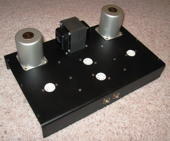
Here's a shot that shows the relative layout of the major components, the flush fasteners and RCA panel jacks.
Out Back:
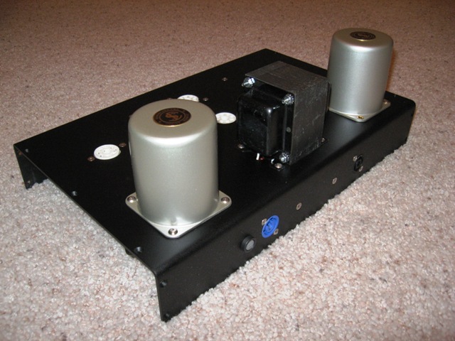
A view from behind. The whole chassis is a little dirty in this picture. Oops!
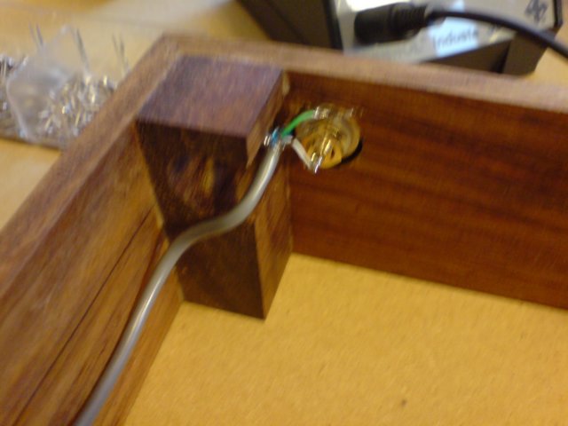
I'm positive it connects to the negative:
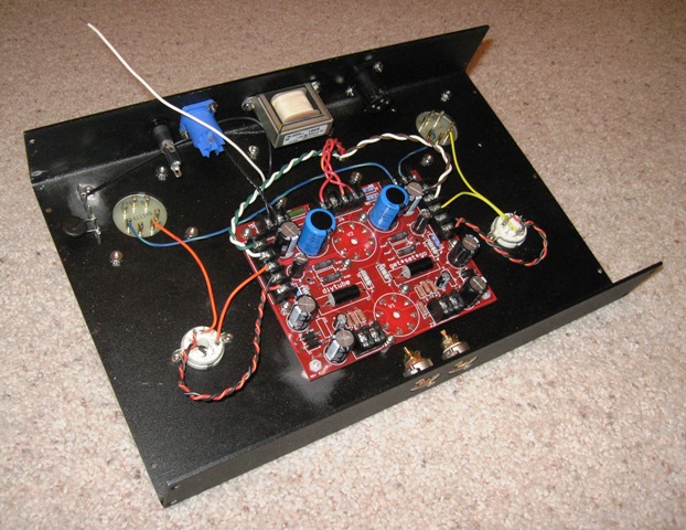
I finally began to wire some of the components. I tried to use some of Morgan Jones' techniques from his book "Building Valve Amplifiers" but my chassis layout didn't accommodate his `ideal' wire routing. Any suggestions on changes to improve wire routing?
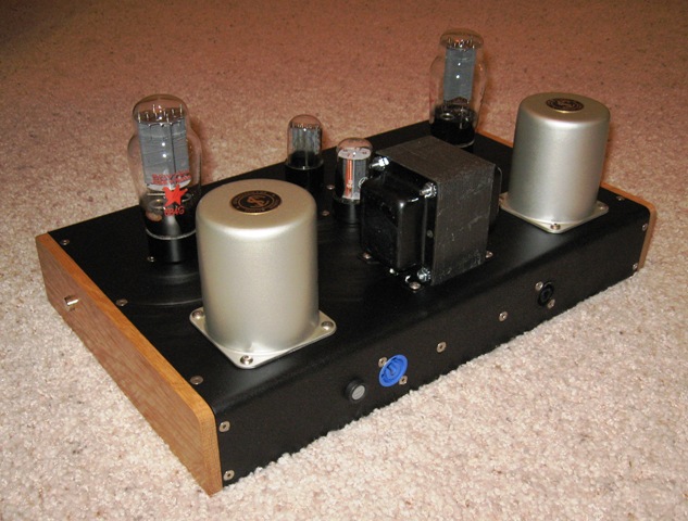
Profiling:
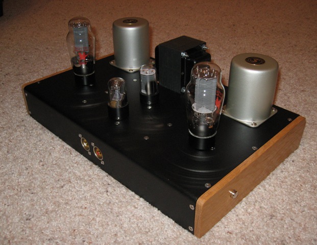
Finally! Sides added to the amplifier as well as the tubes. The silver button on the wooden side is the power toggle. The amp doesn't have a power indicator.
Front & Center:
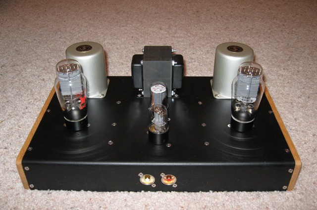
The amp turned out nearly like I envisioned. Perhaps I should have staggered the power tubes in a little to show off those fancy looking OPTs a little bit. In fact, the whole amp could be a little narrower I guess.
Back, Again:
Another view from behind. I meant to plug in the power cord (blue jack) and speaker wires (black jack). Next time...
Bottoms Up!:
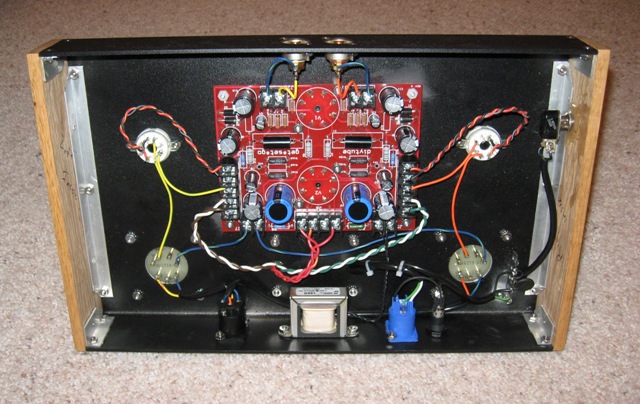
Last but not least, a view under the hood. I know it's sorta small, but if any of you guys have suggestions on re-routing wires or anything else, please let me know.
The G*S*G has been one of my favorite amps to build. If I had been more diligent about keeping up with it I probably could have cranked the finished product out in a few weeks rather than 2/3 of a year, but it was a lot of fun, as always.
Let me know if you have any suggestions of questions. Thanks guys!
Top-Down 3/4 View:
Here's a shot that shows the relative layout of the major components, the flush fasteners and RCA panel jacks.
Out Back:
A view from behind. The whole chassis is a little dirty in this picture. Oops!
I'm positive it connects to the negative:
I finally began to wire some of the components. I tried to use some of Morgan Jones' techniques from his book "Building Valve Amplifiers" but my chassis layout didn't accommodate his `ideal' wire routing. Any suggestions on changes to improve wire routing?
Profiling:
Finally! Sides added to the amplifier as well as the tubes. The silver button on the wooden side is the power toggle. The amp doesn't have a power indicator.
Front & Center:
The amp turned out nearly like I envisioned. Perhaps I should have staggered the power tubes in a little to show off those fancy looking OPTs a little bit. In fact, the whole amp could be a little narrower I guess.
Back, Again:
Another view from behind. I meant to plug in the power cord (blue jack) and speaker wires (black jack). Next time...
Bottoms Up!:
Last but not least, a view under the hood. I know it's sorta small, but if any of you guys have suggestions on re-routing wires or anything else, please let me know.
The G*S*G has been one of my favorite amps to build. If I had been more diligent about keeping up with it I probably could have cranked the finished product out in a few weeks rather than 2/3 of a year, but it was a lot of fun, as always.
Let me know if you have any suggestions of questions. Thanks guys!
- nineno
- Posts: 117
- Joined: Sat Aug 02, 2003 10:59 pm
I get similar from Conrad.de
![]() by hembrook » Sat Feb 09, 2008 5:48 pm
by hembrook » Sat Feb 09, 2008 5:48 pm
separks wrote:Who's your supplier for the Neutrik RCA connectors? Pretty slick looking.
I get similar from Conrad.de

http://www1.conrad.de/conrad/layout2/detail.fh?fh_secondid=b2c302891&fh_view_size=50&action=search&fh_source_url=%2fconrad%2flayout2%2findex.fh%3ffh_host%3dwww1.conrad.de%26fh_session%3d%2fscripts%2fwgate%2fzcop_b2c%2f~flN0YXRlPTI5ODMzOTM4OTQ%3d&layout=layout2&~template=pcat_area_s_browse&p_searchstring_artnr=&fh_sort_by=&fh_host=www1.conrad.de&zhmmh_area_kz=&https_reload=on&fh_eds=%c3%9f&fh_session=%2fscripts%2fwgate%2fzcop_b2c%2f~flN0YXRlPTI5ODMzOTM4OTQ%3d&p_page_to_display=DirektSearch&fh_location=&fh_search=%09%0d%0aCINCH-EINBAUBUCHSE+METALL&fh_refview=search
- hembrook
- Posts: 122
- Joined: Wed Oct 31, 2007 3:36 pm
19 posts
• Page 2 of 2 • 1, 2
Who is online
Users browsing this forum: No registered users and 4 guests