DHT Christmas: My First SET

2nd harmonics for the masses

DHT Christmas: My First SET

Postby Shannon Parks » Mon Dec 25, 2006 7:36 am

Wow - just looked at the picture on the fridge yesterday and it's me holding my first diy ST35, Christmas '01. Looks like a 5th anniversary of sorts. Anyhow, here's what I've been working on. Details on design: 6B4 x2, 6SL7, 6AX5GT, PA774, James 6115 x2, along the lines of the JE Labs Simple 2A3.

Image

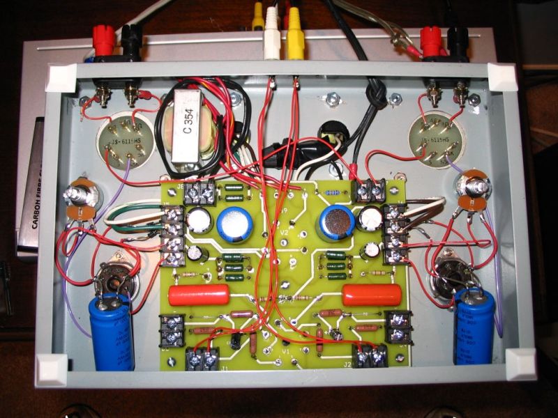
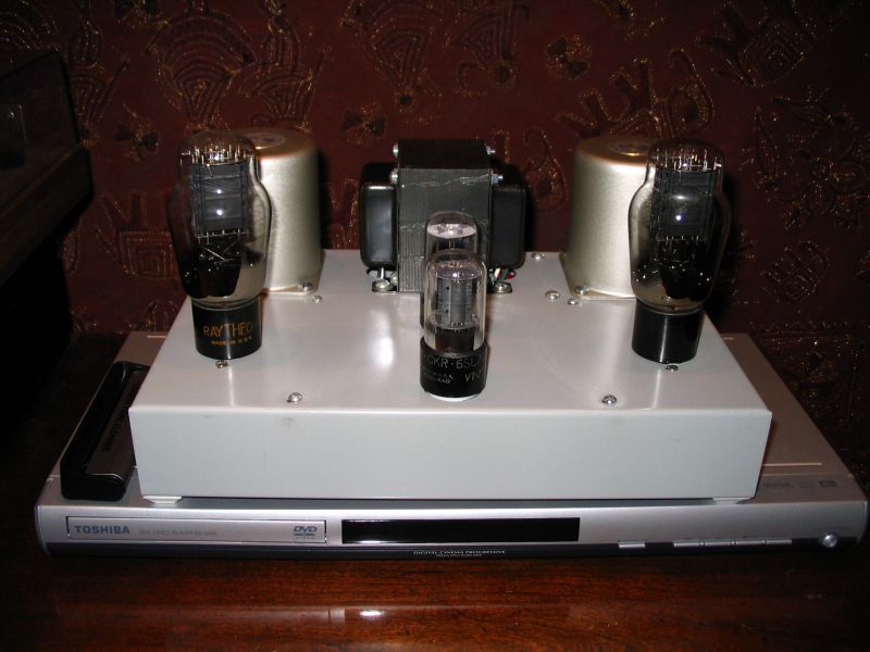
A DHT SET for the masses? Hopefully. The prototype PCB has undergone a revision to switch to DC filaments for the 6B4s. Too much hum for a wiper pot control. The 6AX5GT is a happy little guy, and truly seems to be a 5Y3 cousin (and cheap as dirt on eBay). The PS does use a choke, the tiny Dyna choke in a CLCRC supply. Totally silent on the horns. How does it sound? Excellent!

Plans are for a PCB with parts list, BOM and schematics. One could make a DHT SET amp, or just build a simple linestage. Limited commerical builds will be available, hopefully, in a color anodized top plate with wood base.
User avatar
Shannon Parks
Site Admin
 
Posts: 3764
Joined: Tue Mar 18, 2003 5:40 pm
Location: Poulsbo, Washington

Postby EWBrown » Tue Dec 26, 2006 7:20 am

Very nice! I'd definitely be interested in purchasing one of the PCBs when they are ready...

Are the 6B4s on or off the PCB? (I'm already thinking of a 2A3 variant) Yellow_Light_Colorz_PDT_02

With DC filaments, is it better to connect the positive or negative filament lead to the "cathode" resistor, or do you use two resistors across the filament, and then use the center connection?


I wasn't able to do anything with my "300B SET on an ST70 chassis" this past long weekend, maybe next weekend. I was going to use AC for the filaments, but have decided to go with DC, and try a couple of nice small 5V, 2A SMPS "bricks" which will fit neatly under the chassis.

/ed B in NH
Real Radios Glow in the Dark
User avatar
EWBrown
Insulator & Iron Magnate
 
Posts: 6389
Joined: Wed Mar 19, 2003 6:03 am
Location: Now located in Clay County, NC !

Postby Shannon Parks » Tue Dec 26, 2006 12:14 pm

EWBrown wrote:Are the 6B4s on or off the PCB? (I'm already thinking of a 2A3 variant) Yellow_Light_Colorz_PDT_02


Seasons Greetings, Ed. They are chassis mounted. The board is a driver, power supply and DC filament supply. So you can use any variant. The cool factor in this design is using a $59 Dynaclone PA774 with its dual 6.3VAC taps for a 6B4. Works great!
User avatar
Shannon Parks
Site Admin
 
Posts: 3764
Joined: Tue Mar 18, 2003 5:40 pm
Location: Poulsbo, Washington

New PCB SE

Postby leadtower » Tue Dec 26, 2006 12:48 pm

Merry Xmas to all. Where is the list for the SE PCB's? Shannon; put me down for a SET of those; I have a check or cash in hand waiting patiently.
leadtower
 
Posts: 200
Joined: Tue Mar 30, 2004 8:39 pm

Postby TerrySmith » Tue Dec 26, 2006 5:26 pm

Hows about a picture of under the hood!
T. Smith
User avatar
TerrySmith
KT88
 
Posts: 973
Joined: Sat Jan 31, 2004 12:51 pm
Location: Maryville TN

Postby Shannon Parks » Tue Dec 26, 2006 6:26 pm

TerrySmith wrote:Hows about a picture of under the hood!


Why my pleasure! Note that I am moving the huge DC filament caps to the PCB. They'll be smaller as these are 100V rated 3300uF monsters. The PCB will be the same size, but the feedback connectors and circuit will be gone (too little gain for that anyhow). The hum pots will become a pair of resistors on the PCB, too.

Image
User avatar
Shannon Parks
Site Admin
 
Posts: 3764
Joined: Tue Mar 18, 2003 5:40 pm
Location: Poulsbo, Washington

nice !

Postby EWBrown » Wed Dec 27, 2006 6:23 am

Nice clean and symmetrical layout, I like it!

Definitely, NFB isn't needed with these SETs, it goes against the "zen" simplicity of the design. Might be needed when using BPTs or pentodes, in pseudo-triode, but it only reduces the gain and alters the sound in all-triode designs.

Sounds like DC filaments is the way to go for any DHTs.

/ed b in NH
Real Radios Glow in the Dark
User avatar
EWBrown
Insulator & Iron Magnate
 
Posts: 6389
Joined: Wed Mar 19, 2003 6:03 am
Location: Now located in Clay County, NC !

Postby Shannon Parks » Wed Dec 27, 2006 6:45 am

I think a 2A3 would be passable on AC and with a hum pot, though zeroing in on the perfect adjustment (just off center) can be tricky. The Vpp on a 6B4 with AC would be 8.9V, whereas a 2A3 would be 3.5V. Currently, this amp has about 2.2V of AC ripple with the dodgy DC filament circuit I rigged up, so I think the 2A3 would not be much worse on AC. But I could only drop the 6B4G on AC to around 14mV of residual hum. Though I swear I saw an ad in Sound Practices for an amp with only 10mV or less of hum. Good grief!

The final DC circuit will use four schottkys in a bridge with a CRC filter. Ripple should be less than 500mV and thus hopefully an easier target with the voltage reference divider. To answer your earlier question, Ed, you definitely need a divider or pot for this, as attaching directly to '+' or '-' ends up giving you loads of hum. I measured 40mV. Funny that Broskie's SE Amp Cad - which has been invaluable for this design - doesn't show this configuration. It just attaches to the '-'.
User avatar
Shannon Parks
Site Admin
 
Posts: 3764
Joined: Tue Mar 18, 2003 5:40 pm
Location: Poulsbo, Washington

Postby EWBrown » Wed Dec 27, 2006 10:27 am

You might be getting a tiny bit of hum induced by those long unshielded input leads, especially as they transit by the C354 choke, and under the power trannie, try twisting them together, that should help. I would SWAG that the final config would have the inputs closer to those on the PCB.

/ed B inNH
Real Radios Glow in the Dark
User avatar
EWBrown
Insulator & Iron Magnate
 
Posts: 6389
Joined: Wed Mar 19, 2003 6:03 am
Location: Now located in Clay County, NC !

Postby Shannon Parks » Wed Dec 27, 2006 12:32 pm

EWBrown wrote:You might be getting a tiny bit of hum induced by those long unshielded input leads, especially as they transit by the C354 choke, and under the power trannie, try twisting them together, that should help. I would SWAG that the final config would have the inputs closer to those on the PCB.

/ed B inNH


Nice catch, Ed. This was a drilling error. After twenty minutes of measuring and drilling this tricky bugger, I realized I put it on the back instead of the front. I was too lazy to fix it, but it was the first thing I measured - no noise is added. The production unit will have inputs on the top of the top plate a couple inches away.
User avatar
Shannon Parks
Site Admin
 
Posts: 3764
Joined: Tue Mar 18, 2003 5:40 pm
Location: Poulsbo, Washington

Postby TomMcNally » Wed Dec 27, 2006 1:22 pm

Shannon -

A couple of questions ...

What are your test conditions when you measure the residual noise ?
After reading your post saying you got 14 mv, I fired up the Boonton and one of my Darlings and I am getting 2.7 mv with the inputs shorted. Measuring across the 8 ohm load resistor on either channel in balanced mode. With headphones, I hear hum, not real happy with it. This is on the small amps with no choke, I may have to change something.

Also - most DC filament circuits I've seen have one side grounded, and no balance pots. Are you saying to leave the filaments floating and use a pot with the wiper grounded ?

... tom
User avatar
TomMcNally
Darling du Jour
 
Posts: 2729
Joined: Sat Nov 19, 2005 2:19 pm
Location: Northfield, NJ

Postby EWBrown » Wed Dec 27, 2006 1:40 pm

The original Bottlehead "Paramour" 2A3 SETs used 2.5VAC with a 50 ohm hum balance pot, and 1.2 K @ 10 Watts "cathode" resistor. The driver tube was one half of a 12AT7, and C4S was an option for the 12AT7, otherwise a 120K (IIRC) plate resistor was used.

For details of the build and assembly, check out Wardsweb's site here:

http://wardsweb.org/audio/paramours.html

There is more than enough detailed info to reverse-engineer this fairly simple (and good) design.


The newest version of this amp uses a slightly different topography, and the C4S (Camille's Cascode Constant Current Source) is standard.

These amps use parallel feed for the 2A3, using a plate loading choke, 3.3 uF , 630VDC coupling cap and 4K to 4/8/16 ohm OPT, which doesn't have to handle any DC current, only AC audio signal.

/ed B in NH
Real Radios Glow in the Dark
User avatar
EWBrown
Insulator & Iron Magnate
 
Posts: 6389
Joined: Wed Mar 19, 2003 6:03 am
Location: Now located in Clay County, NC !

Postby Shannon Parks » Wed Dec 27, 2006 2:31 pm

TomMcNally wrote:What are your test conditions when you measure the residual noise ?


Same as your test, both balanced and unbalanced (no difference in this setup). Both shorted and Boonton loaded - no diff. I think hum needs to be at or below 1mV.

TomMcNally wrote:Also - most DC filament circuits I've seen have one side grounded, and no balance pots. Are you saying to leave the filaments floating and use a pot with the wiper grounded ?


Correct - the DC filaments are referenced to an in-between voltage that nulls out the hum (even the hum from the power supply which seems secondary at this point).

I hadn't seen this either, but I gave it a shot for the SWAG of it. Works great. But Monday night I did stumble across some Japanese DHT schematics that use this method, though it was for a driver DHT and not a power tube.
User avatar
Shannon Parks
Site Admin
 
Posts: 3764
Joined: Tue Mar 18, 2003 5:40 pm
Location: Poulsbo, Washington

Postby EWBrown » Thu Dec 28, 2006 6:19 am

I take it that the 6AX5 and 6SL7 have AC on the filaments, and the 6B4Gs have DC? I wonder if it would be beneficial to use DC on the 6SL7 as well (and perhaps on the 6AX5, though that isn't going to make a dime's worth of difference, except for circuit simplicity).


The "Voice of Music" console amp power trannie, that I used on the 6EM7 PP amp, would be perfect for this kind of circuit, it has three separate 6.3VAC filament windings, one 5VAC rectifier winding, 310-0-310 VAC and a separate 120VAC secondary, which was intended to power the AM/FM tuner, which used the series string AC/DC type circuitry to keep it "cheap"... The 120VAC winding could be used to power a small linestage, thusly isolating it further from the AC power line and breaking any ground loops even further.


The latest" totally tubular" foundling : A Blonder-Tongue (best known for UHF TV tuners) 10W PP 6V6 mono integrated amp and a separate AM/FM mono tuner. Looks in good shape, though I haven't yet given it the smoke test.

IF anything, it is either a "collectable" or at worst case, a parts donor.
Judging from the puny OPT and the profusion of ceramic disk caps, I doubt that it's going to win any "golden ear" audiophile awards Yellow_Light_Colorz_PDT_02

I'll post pictures sometime soon.


/ed B in NH
Real Radios Glow in the Dark
User avatar
EWBrown
Insulator & Iron Magnate
 
Posts: 6389
Joined: Wed Mar 19, 2003 6:03 am
Location: Now located in Clay County, NC !

Postby Shannon Parks » Thu Dec 28, 2006 6:36 am

EWBrown wrote:I take it that the 6AX5 and 6SL7 have AC on the filaments, and the 6B4Gs have DC?


This is indeed correct, Ed. The AC filaments are raised to the 6B4 cathode voltage (minus a diode drop).

BTW, here's the PSU Designer II file:
http://www.diytube.com/forumpix/james6B4G.psu

B+ comes from C3. 20mVpp of ripple.

EWBrown wrote:I wonder if it would be beneficial to use DC on the 6SL7 as well (and perhaps on the 6AX5, though that isn't going to make a dime's worth of difference, except for circuit simplicity).


In this case with the PA774, I didn't want to add anymore inefficiency in the rectifier circuit, particularly with the 6B4G & 6AX5GT sharing a 2.5A rated tap. Right now, it's looking like the pot/resistive divider should do wonders so I haven't needed to tweak the B+ ripple or worry about the AC on the 6SL7. But since the overall gain is only 15dB (IIRC), this probably won't ever be a problem. But who knows? I could be at the point of diminishing returns right now. Hopefully I can squash the DC filament ripple under 500mV and get the residual hum to 500uV. I'll be happy with that.
User avatar
Shannon Parks
Site Admin
 
Posts: 3764
Joined: Tue Mar 18, 2003 5:40 pm
Location: Poulsbo, Washington

Next

Return to get*set*go

Who is online

Users browsing this forum: No registered users and 14 guests