When sweeping, 80kHz, 100kHz and 140kHz would return no distortion measurement. Going into Local mode, I could observe this problem with just using the keyboard controls. I could set up 80kHz, 1V out, and the analyzer would measure 1V. I would then press the DIST button, and the unit would show a LED box (what it always shows while taking a measurement). But it would remain on the box. So I didn't have a GPIB comm problem, but I did have a hardware problem.
Thinking it over, the repetition of the problem made me think it was a notch filter issue. The notch filter in the Boonton filters out the fundamental frequency for the analyzer. What is leftover, is distortion and noise. A misaligned notch filter doesn't attenuate the fundamental enough, allowing it to be part of the distortion measurement.
Go to page 5-24, sections 5-58,59 of the Boonton 1121 manual (other than a handful of features, the 1120 & 1121 manuals are the same, but the 1120 is more legible). The manual refers to the Notch board as A3 but it is actually A2. Luckily, the adjustment pots are on the top so you don't need the extender board. Follow all the instructions minus the ones that refer to a wave analyzer.
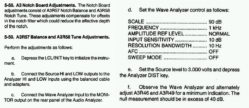
Luckily, I have a FFT function on my scope, so I did run a BNC-to-BNC fron the Boonton monitor to my scope, looking at the 1kHz fundamental. Ultimately, while handy, it is not needed. It jitters around too much (at least on my rig) to be very useful. All you need to do is now tweak the Balance and Tune pots, aiming for the lowest distortion from the analyzer window. The manual says you need 40dB of rejection, and my FFT always looked to be bouncy between 30 - 40 dB, so the low THD analyzer number became my target. Looking at my unit on the scope, I only had 10dB of rejection at the fundamental - yuck! So adjust the one closest to you first with a trimmer. Pot sensitivity is HIGH! So very small turns are in order. Don't worry, you end up rotating it back and forth until you hit the sweet spot. Then switch to the further pot and do the same, but the first pot seems to be the main pot. Repeat if necessary. I was hitting a target of .0023% with ocassional flickers to .0022%, but your source can vary greatly from this. Just tweak the notch filter best you can. We can worry about the rest later.
Note, do this test at 1kHz with 3V output per the manual. I experimented with tuning the notch filter at other frequencies (eg 100kHz) and that didn't work well. And lastly, if you don't have any problems making distortion measurements, I wouldn't bother doing this fix. This is a repair more than a tweak. Good luck!
Shannon

