Integrated Amp: Mark III & PAS

for Dynaco Mark II/III/IV and DIY PP monoblocks

Postby ChrisK » Thu May 21, 2009 7:44 am

EWBrown wrote:You new schematic is right-on!

Rather than having a resistor in parallel with the SS rectifiers, perhaps a 10 ohm, 1W resistor in series with each diode would help absorb some of the transients, or just skip the added resistors altogether.


Understood, thanks. Thanks for checking the schematic; I really like this solution!

Chris
User avatar
ChrisK
 
Posts: 115
Joined: Sun Mar 23, 2008 5:57 pm
Location: Laguna Beach, CA

Bias Taps

Postby ChrisK » Thu May 21, 2009 7:49 am

EWBrown wrote:Are the 70V bias taps a separate winding, or are they taken off the 400V windings?


Each 400v winding has a 70v bias tap.

Hey, I really appreciate your interest and help with this!

Regards,

Chris
User avatar
ChrisK
 
Posts: 115
Joined: Sun Mar 23, 2008 5:57 pm
Location: Laguna Beach, CA

Chassis Layout

Postby ChrisK » Fri May 22, 2009 11:03 am

Question: Can two Mark III amps be integrated on a single chassis? Maybe. How about something like this:

Image

15.5 " wide by 14" deep. Why? Because there's only so much shelf space available. After 38 years of marriage, compromise becomes a survival skill. 8-)

As always, comments/critique would be welcome.

Thanks,

Chris
User avatar
ChrisK
 
Posts: 115
Joined: Sun Mar 23, 2008 5:57 pm
Location: Laguna Beach, CA

Postby TomMcNally » Fri May 22, 2009 12:02 pm

No technical reason it won't work ... just gonna be HEAVY !
My bedroom bureau warped under the weight of my 60 pound
300B amp ... ha !

Very cool - should sound great !
User avatar
TomMcNally
Darling du Jour
 
Posts: 2729
Joined: Sat Nov 19, 2005 2:19 pm
Location: Northfield, NJ

Postby ChrisK » Fri May 22, 2009 12:21 pm

TomMcNally wrote:No technical reason it won't work ... just gonna be HEAVY !
My bedroom bureau warped under the weight of my 60 pound
300B amp ... ha !

Very cool - should sound great !


Yeh, Tom, you're not kidding about the weight! Fortunately, when I built some living room cabinets I stressed some "special places" to support iron. 2x4 and 3/4" plywood all prettied up to look like a built-in.

I'm encouraged by your comment regarding the technical aspects of the layout. Thanks very much...

Chris
User avatar
ChrisK
 
Posts: 115
Joined: Sun Mar 23, 2008 5:57 pm
Location: Laguna Beach, CA

Postby nyazzip » Sat May 23, 2009 12:43 am

No technical reason it won't work ... just gonna be HEAVY !


wouldn't you also likely have less EMF/AC noise interferance with separate mono units? when i first started thinking about amps about a year and a half ago i had a similar question about the monoblock concept
<i>the poor craftsman blames his tools</i>
User avatar
nyazzip
KT88
 
Posts: 1073
Joined: Wed Jan 09, 2008 1:24 am

Postby ChrisK » Sat May 23, 2009 7:47 am

nyazzip wrote:
No technical reason it won't work ... just gonna be HEAVY !

wouldn't you also likely have less EMF/AC noise interferance with separate mono units?


"Less likely"? Good question, made me think.

What you're really asking is: "Aren't monoblocks inherently better because there would be less EMF/AC noise interference between the channels"?

Originally, the Mark III's were manufactured as monoblocks not for reasons of noise suppression, but to make them affordable. In the Sixty's (of which I am a product), a whole generation of excellent and highly successful amps combined two channels onto one chassis. The good ones, I'm sure, were quieter than the Dynacos.

I have a Harman-Kardon Citation II which is dead-quiet. Amazing, considering the circuitry crammed into the chassis! My point is, it can be done but the challenge (and fun) is to do it properly.

With attention to detail including the use of a power toroid, transformer orientation, more generous spacing between components, shielding and build quality, a pair of Mark III's on a single chassis will be quiet. Just imagine two monoblocks sitting next to each other.

Regards,

Chris
User avatar
ChrisK
 
Posts: 115
Joined: Sun Mar 23, 2008 5:57 pm
Location: Laguna Beach, CA

Postby TomMcNally » Sat May 23, 2009 2:06 pm

I think MK-III's are mono ... because they came out before
stereo was invented ... all you needed was one amp, one speaker.
User avatar
TomMcNally
Darling du Jour
 
Posts: 2729
Joined: Sat Nov 19, 2005 2:19 pm
Location: Northfield, NJ

Postby ChrisK » Sat May 23, 2009 3:46 pm

TomMcNally wrote:I think MK-III's are mono ... because they came out before
stereo was invented ... all you needed was one amp, one speaker.


You're right, Tom.

That's one of the reasons I want to keep to discreet channels. I have a PAM that will be connected to a '78 needle to play lots of Big Band albums that I inherited. But I also have a need for '60's classic rock, so I'm trying for the best of both worlds.
User avatar
ChrisK
 
Posts: 115
Joined: Sun Mar 23, 2008 5:57 pm
Location: Laguna Beach, CA

possible bias voltage problem ?

Postby EWBrown » Sat May 23, 2009 5:13 pm

EWBrown wrote:
Are the 70V bias taps a separate winding, or are they taken off the 400V windings?

================

Each 400v winding has a 70v bias tap.

Hey, I really appreciate your interest and help with this!

Regards,

Chris


Just thinking about the two separate 400V secondary windings with the 70V "bias" taps....

With the full wave rectifier bridge (and it doesn't really make any in this case, whether it is all SS or hybrid) that the 70V taps won't readily generate -70V, the voltage will be positive and unbalanced, in reference to ground. I'll have to look this one over, but at a glasnce, it appears that it cannot generate a negative voltage, without some added complexity. Stay tuned...


You may need a separate transformer to generate tthe -70V (adjustable) bias voltage. The current requirement is rather small, most of the DC curent would be consumed by the bias pots and the divider resistors, the grids themselves take very little current, on the order of microamperes at moat.
Real Radios Glow in the Dark
User avatar
EWBrown
Insulator & Iron Magnate
 
Posts: 6389
Joined: Wed Mar 19, 2003 6:03 am
Location: Now located in Clay County, NC !

Re: possible bias voltage problem ?

Postby ChrisK » Sat May 23, 2009 5:36 pm

EWBrown wrote:
Just thinking about the two separate 400V secondary windings with the 70V "bias" taps....
Stay tuned...


Thanks for thinking about that...I wouldn't know what to do. You bet I'll stay tuned!

Chris
User avatar
ChrisK
 
Posts: 115
Joined: Sun Mar 23, 2008 5:57 pm
Location: Laguna Beach, CA

Re: possible bias voltage problem ?

Postby ChrisK » Sun May 24, 2009 8:57 am

EWBrown wrote:
EWBrown wrote: You may need a separate transformer to generate tthe -70V (adjustable) bias voltage..


Instead of 70v, why not 50v which is what the original Mark III power transformer provides.

Might be easiest for me to get something like a Hammond 167G100, fairly small footprint, 100v with CT, so I'd have the stock 50v each side to work with. Not that pricey from Mouser.

Chris
User avatar
ChrisK
 
Posts: 115
Joined: Sun Mar 23, 2008 5:57 pm
Location: Laguna Beach, CA

Postby Ty_Bower » Sun May 24, 2009 9:53 am

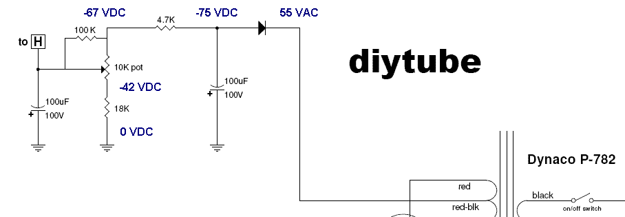
I think Ed must have been referring to the approximately -70V DC bias supply after half wave rectification, filtering, and resistive losses. My Mark III has a ~55V AC tap for the input to the bias supply.

Image
"It's a different experience; the noise occlusion, crisp, clear sound, and defined powerful bass. Strong bass does not corrupt the higher frequencies, giving a very different overall feel of the sound, one that is, in my opinion, quite unique."
User avatar
Ty_Bower
KT88
 
Posts: 1494
Joined: Wed Mar 21, 2007 2:50 pm
Location: Newark, DE

Separate BIAS Trans

Postby ChrisK » Sun May 24, 2009 9:53 am

Maybe simple is best. How about this if we're concerned about using the 70v tap from the 400v winding?

Image

Chris
User avatar
ChrisK
 
Posts: 115
Joined: Sun Mar 23, 2008 5:57 pm
Location: Laguna Beach, CA

Postby ChrisK » Sun May 24, 2009 10:17 am

Ty_Bower wrote:I think Ed must have been referring to the approximately -70V DC bias supply after half wave rectification, filtering, and resistive losses. My Mark III has a ~55V AC tap for the input to the bias supply.


I don't think that's it. I have a toroid that has two seperate 400V windings for each B+ supply. Each has a 70v A/C tap for the bias supply, and Ed has some concern that these might not work because of the "Hybrid" rectifier we're using (see earlier post). At least that's what I think is going on, but obviously I'm no expert.

To take the easy way out, I'm suggesting that I add a 100v CT trannie that will supply the two bias supplies needed, one from each side of the CT. That should supply approx. -70V DC similar to what you're suggesting, I think.

Thanks for the help,

Chris
User avatar
ChrisK
 
Posts: 115
Joined: Sun Mar 23, 2008 5:57 pm
Location: Laguna Beach, CA

PreviousNext

Return to poseidon

Who is online

Users browsing this forum: No registered users and 11 guests