Replaced R5 and it blew again. I let the magic out.
I have a .47uf instead of a .22uf in at C1, could this cause it to blow?
Once the delay closed the contacts and let power flow to the Rectifier, R5 went up. Is there a problem with my PS?
I keep going over it and am not seeing the problem.
Any help would be deeply appreciated.
Thanks,
Jason
SOON!
46 posts
• Page 2 of 4 • 1, 2, 3, 4
![]() by battradio » Sat Mar 28, 2009 3:24 pm
by battradio » Sat Mar 28, 2009 3:24 pm
Hi ,
Do you have the tubes in the sockets if you do ,remove them .Its very hard to harm a 120pf cap .Are the two leads coming from the output transformer that are thumb nuted together insulated from each other ,a short at that point is shorting out the output ,
Mark
Do you have the tubes in the sockets if you do ,remove them .Its very hard to harm a 120pf cap .Are the two leads coming from the output transformer that are thumb nuted together insulated from each other ,a short at that point is shorting out the output ,
Mark
-

battradio - KT88
- Posts: 927
- Joined: Tue Mar 10, 2009 12:58 am
- Location: near ST.Louis MO.
![]() by JW34 » Sat Mar 28, 2009 3:36 pm
by JW34 » Sat Mar 28, 2009 3:36 pm
battradio wrote:Hi ,
Do you have the tubes in the sockets if you do ,remove them .Its very hard to harm a 120pf cap .Are the two leads coming from the output transformer that are thumb nuted together insulated from each other ,a short at that point is shorting out the output ,
Mark
Hello Mark,
I actually changed it up and ran the 16ohm tap of the output transformer back to the NF (I) on the circuit board. The 4ohm tap is nutted so there is no short betwwen them.
As far as the part #'s, they are based off of Neds schematic / parts list for the poseidon board.
I could snap a pic of the wiring, but I thought it would be easier to follow the wiring drawing. Let me know if a pic would be better.
Jay
- JW34
- Posts: 106
- Joined: Fri Feb 01, 2008 5:30 pm
- Location: Chicagoland
![]() by JW34 » Sat Mar 28, 2009 7:59 pm
by JW34 » Sat Mar 28, 2009 7:59 pm
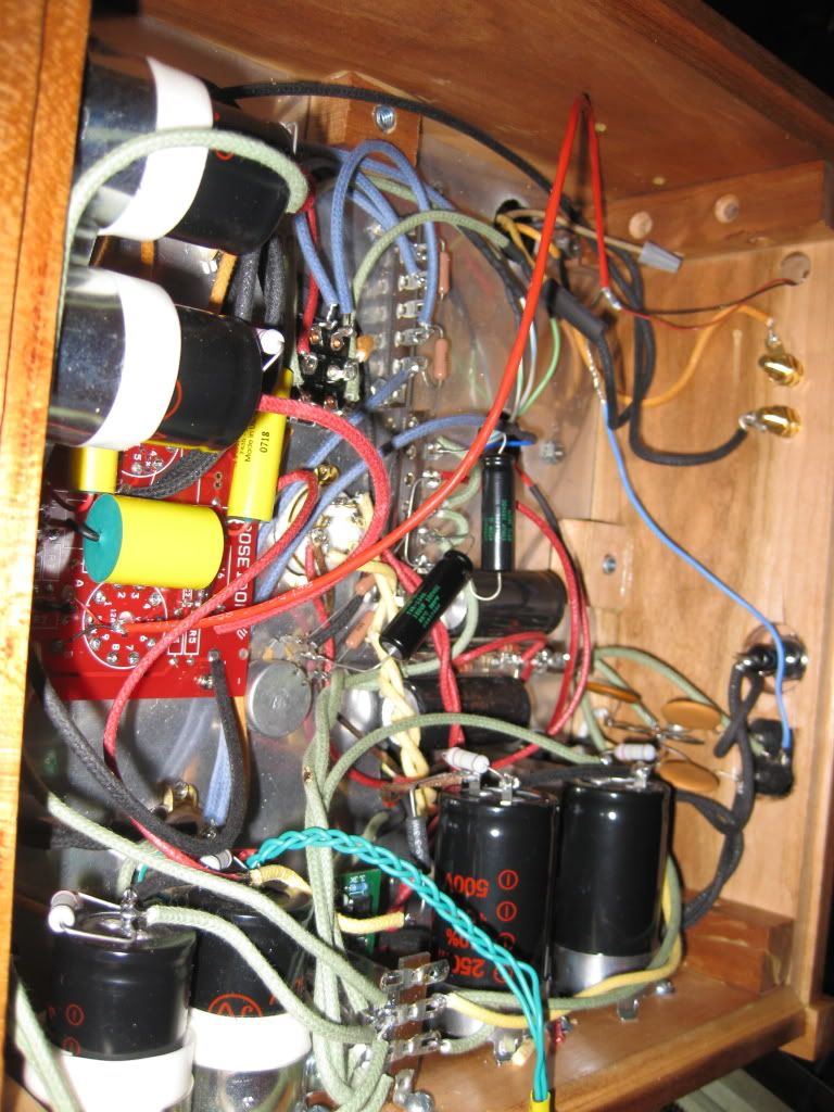
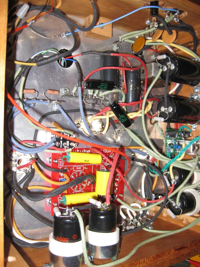
Cool. Please forgive me because I know the wiring dosen't look the neatest. This is my first build so please understand. Also, everything is not zipped up and tied down yet.
Here's the schematic:
http://www.diytube.com/unidriver/poseidon-tz.pdf
Top Pics:
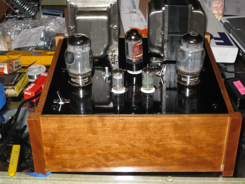
http://i579.photobucket.com/albums/ss238/jw343/top3.jpg
Bottom Pics:
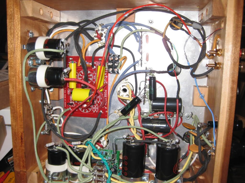
More:
http://i579.photobucket.com/albums/ss23 ... angle2.jpg
http://i579.photobucket.com/albums/ss23 ... angle3.jpg
http://i579.photobucket.com/albums/ss23 ... angle4.jpg
Thanks,
Jason
Here's the schematic:
http://www.diytube.com/unidriver/poseidon-tz.pdf
Top Pics:
http://i579.photobucket.com/albums/ss238/jw343/top3.jpg
Bottom Pics:
More:
http://i579.photobucket.com/albums/ss23 ... angle2.jpg
http://i579.photobucket.com/albums/ss23 ... angle3.jpg
http://i579.photobucket.com/albums/ss23 ... angle4.jpg
Thanks,
Jason
- JW34
- Posts: 106
- Joined: Fri Feb 01, 2008 5:30 pm
- Location: Chicagoland
![]() by Ty_Bower » Sat Mar 28, 2009 9:04 pm
by Ty_Bower » Sat Mar 28, 2009 9:04 pm
B+ voltage looks a little high. I think the manual specified about 500 volts at the plate of the output tubes; you are showing about 560. Your heater voltages are a bit high too. They should be around 6.3VAC, not 6.8. While this isn't the end of the world, the tubes will last longer if you can at least get the heater voltage back into spec. It's kind of a pain - the old Dynaco power transformers were designed for 117V coming out of the wall. Most homes nowadays will run five to ten percent higher than that. Are your transformers original Dynaco iron, or are they modern reproductions?
R5 shouldn't be frying. That's part of the feedback circuit. No significant power should be flowing here.
Since you didn't build on the original Dynaco chassis, I'd imagine it would be VERY easy to accidentally get the phase of the output tubes "wrong" with respect to the feedback circuit. This would almost certainly cause the amp to oscillate wildly. I'd suspect that a 60 watt amp in full oscillation would fall into the "not good thing" category. All that healthy capacitance you've built into the PSU would only make it more exciting. Do you have a dummy resistive load on the outputs for your initial testing?
Edit... I'm staring at your pictorial diagram of your chassis wiring. It looks like you've got F going to the KT88 with the blue/white and green/white OPT leads. If so, that is incorrect. F must go to the KT88 with the solid blue and solid green wires. G goes to the tube with the blue/white and green/white.
"It's a different experience; the noise occlusion, crisp, clear sound, and defined powerful bass. Strong bass does not corrupt the higher frequencies, giving a very different overall feel of the sound, one that is, in my opinion, quite unique."
-

Ty_Bower - KT88
- Posts: 1494
- Joined: Wed Mar 21, 2007 2:50 pm
- Location: Newark, DE
![]() by JW34 » Sat Mar 28, 2009 10:09 pm
by JW34 » Sat Mar 28, 2009 10:09 pm
[quote="Ty_Bower"] Are your transformers original Dynaco iron, or are they modern reproductions?
They are the origanal Dynaco Iron. How would I lower the voltage?
R5 shouldn't be frying. That's part of the feedback circuit. No significant power should be flowing here.
I'm using the 16ohm tap from the OPT directly to I as the Feedback. is this O.K.?
Do you have a dummy resistive load on the outputs for your initial testing?
I'm using a 8 ohm 20 watt non-ind. resistor for the speaker terminals.
Edit... I'm staring at your pictorial diagram of your chassis wiring. It looks like you've got F going to the KT88 with the blue/white and green/white OPT leads. If so, that is incorrect. F must go to the KT88 with the solid blue and solid green wires. G goes to the tube with the blue/white and green/white.[/quote]
You are correct. They are wired like you see it. I will rewire that in the morning and recheck.
Thank you!
- JW34
- Posts: 106
- Joined: Fri Feb 01, 2008 5:30 pm
- Location: Chicagoland
![]() by Ty_Bower » Sun Mar 29, 2009 5:46 am
by Ty_Bower » Sun Mar 29, 2009 5:46 am
To lower the line voltage, I'd use an autoformer. Get a cheap 12V transformer; something like the 3A one they sell at Radio Shack should work great. Connect the two windings (primary and secondary) together in series and in phase. Put the line voltage across the whole thing, and take your reduced voltage off the primary winding. Build the whole contraption inside a grounded metal or double-insulated box. There are a few threads which discuss the idea at length. Note the second link suggests a wiring scheme different from what I just described.
http://www.diyaudio.com/forums/showthre ... did=133843
http://www.geofex.com/Article_Folders/v ... ntvolt.htm
The Poseidon manual indicates the feedback is taken directly from the 16 ohm tap back to point 'I'. How is your feedback wiring different from the way it is supposed to be? I don't have my Mk3 open in front of me to see if I did anything different. Do you have the 680 ohm resistor installed between the 16 ohm tap and ground?
"It's a different experience; the noise occlusion, crisp, clear sound, and defined powerful bass. Strong bass does not corrupt the higher frequencies, giving a very different overall feel of the sound, one that is, in my opinion, quite unique."
-
Ty_Bower - KT88
- Posts: 1494
- Joined: Wed Mar 21, 2007 2:50 pm
- Location: Newark, DE
![]() by Writer Frog » Sun Mar 29, 2009 1:04 pm
by Writer Frog » Sun Mar 29, 2009 1:04 pm
JW34 wrote:........
V2
1. Was 334V then accidently touch pin 2 & 3 on Valve 4 (KT-88), saw flash and then voltage when up to 514V and burned up the 12BH7...YAHOO! I hope nothing on the board got fried.
3. Showing 0V
4,5,9.....?
V3 an V4
1. 3V
2. 6.83
3. 563
4. 565
5. -65
6. -65
7. 6.83
8. 3V
So, did you replace the burned out valve? What are the voltages on the 12BH7 now?
Also, the 3V readings on pins 1 and 8 on V3 and V4 indicate that the output valves are conducting 300mA each! (Cathode Current = 3V / 10ohms). I would be VERY worried about this if I were you. :?
I would also check the DC voltage on the 16ohm output (Yellow) from the A-435. Assuming that the voltage readings on the V1 are correct, the only way the R5 can be burned up is that there is substantial DC voltage coming from the A-435.
Matt
-

Writer Frog - Posts: 95
- Joined: Mon Mar 06, 2006 9:17 am
![]() by Ty_Bower » Sun Mar 29, 2009 1:58 pm
by Ty_Bower » Sun Mar 29, 2009 1:58 pm
JW34 wrote:As far as the 680ohm resistor, it is not in place. will a 1/4 watt do?
For some reason I decided to use a 2 watt rated part when I did mine. I bought it from Mouser along with a bunch of other stuff - I used Mouser part number 282-680-RC.
Doing the math, I believe you can get a 45 volt signal out the 16 ohm tap (peak volts to ground). Dropping that across a 680 ohm resistor results in 65 mA of current, and just under three watts dissipated in the resistor. I suppose in hindsight maybe I should have used a 3 watt part instead? In any event, average power will be much lower, but I'd still be inclined to go with something bigger than a 1/4 watt.
"It's a different experience; the noise occlusion, crisp, clear sound, and defined powerful bass. Strong bass does not corrupt the higher frequencies, giving a very different overall feel of the sound, one that is, in my opinion, quite unique."
-
Ty_Bower - KT88
- Posts: 1494
- Joined: Wed Mar 21, 2007 2:50 pm
- Location: Newark, DE
![]() by Ty_Bower » Sun Mar 29, 2009 2:10 pm
by Ty_Bower » Sun Mar 29, 2009 2:10 pm
MassMat wrote:Also, the 3V readings on pins 1 and 8 on V3 and V4 indicate that the output valves are conducting 300mA each! (Cathode Current = 3V / 10ohms). I would be VERY worried about this if I were you.
I would also check the DC voltage on the 16ohm output (Yellow) from the A-435. Assuming that the voltage readings on the V1 are correct, the only way the R5 can be burned up is that there is substantial DC voltage coming from the A-435.
If his amplifier were oscillating (as it would certainly be doing in the presence of 20 dB positive feedback) the output tubes should be conducting heavily. I could believe they might be drawing 300 mA each for as long as the rectifier would tolerate it - which shouldn't be very long.
Again, under sustained full output conditions (oscillation) there will be significant AC voltage present at the output taps. If you've got 45 volts from peak to ground, you might have ~15 mA current through R5. That's well over half a watt and could possibly fry a 1/4 watt rated resistor.
"It's a different experience; the noise occlusion, crisp, clear sound, and defined powerful bass. Strong bass does not corrupt the higher frequencies, giving a very different overall feel of the sound, one that is, in my opinion, quite unique."
-
Ty_Bower - KT88
- Posts: 1494
- Joined: Wed Mar 21, 2007 2:50 pm
- Location: Newark, DE
![]() by JW34 » Sun Mar 29, 2009 5:13 pm
by JW34 » Sun Mar 29, 2009 5:13 pm
Sorry, my radiator cracked, sump pump went out and my wife's blower motor went out. FUN! All fixed now.
Anyway, I changed F & G around and R5 is not going up in smoke anymore. As far as Pin 1 from the 6550's, I'm still getting 3VDC on one and 7-8VDC on the other.
Alos, I'm getting no voltage on pins 1 of both V1 & V2.
What did I kill, the 6550's & the Rectifier due to Oscillation?
I'm glad I plugged in the 6550's instead of the KT-88's or KT-90's.
I'm not glad that I'm an idiot.
Is my Bias circuit O.K.? I have both 100uf caps grounded to the same side. Ihope this is alright.
How the hell do you guys figure this stuff out?
Thanks,
Jay
- JW34
- Posts: 106
- Joined: Fri Feb 01, 2008 5:30 pm
- Location: Chicagoland
46 posts
• Page 2 of 4 • 1, 2, 3, 4
Who is online
Users browsing this forum: No registered users and 9 guests