Page 1 of 1

Diode

PostPosted: Sat Feb 07, 2009 10:07 am
by 6B4G
Hi to all.
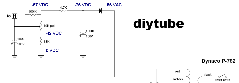
Can anyone tell me if the diode between the red/blk of the opt and the 4.7K + 100uF needed. If so what would be the value?

Thanks

PostPosted: Sat Feb 07, 2009 1:51 pm
by Ty_Bower
I believe you are referring to the diode shown in this schematic?

Image

That diode is absolutely critical. It is required in order to have a functioning negative bias supply. Without it, your output tubes will be destroyed in very short order. I used a UF4007 on mine, but that's probably more than you need. A 1N4003 would probably work fine too, but UF4007 are cheap, so who cares. The diode will see about 155 volts peak on the inverse swing, and the current draw is extremely low - after the initial turnon surge, about 90 mA peak to keep the caps charged.

PostPosted: Sat Feb 07, 2009 4:24 pm
by Geek
EEEEEEEEK! :o

In that circuit, please tie a 100K resistor from the trimmer top (where it meets the 4.7K resistor) and the wiper.

As is, if the wiper lifts (dirt, etc.), you lose bias AND your output tubes.

With the 100K "protective" resistor, if it lifts, the tubes just cutoff :)

Cheers!

PostPosted: Sat Feb 07, 2009 4:57 pm
by Ty_Bower
Geek wrote:please tie a 100K resistor from the trimmer top (where it meets the 4.7K resistor) and the wiper.

Good advice. Why didn't I recognize that before?

PostPosted: Sun Feb 08, 2009 3:09 am
by 6B4G
Thanks for that guys.
Are there any more things I should do, that aren't on the schematics? Yellow_Light_Colorz_PDT_14 [/url]

http://s570.photobucket.com/albums/ss149/6b4g/?action=view&current=bias_circuit.gif

PostPosted: Sun Feb 08, 2009 8:27 pm
by Ty_Bower
Some people have trouble getting enough negative bias voltage with the circuit as shown. It depends on which brand KT88 you've used. The usual cure is to replace the 4.7K resistor (between the pot and the diode) with a smaller value, often 2k or 1k. Mine works fine as shown, but I will admit I need to keep the bias pot turned nearly all the way counter-clockwise. You might want to just start with a 2k and you won't have to worry about it later.

Some have suggested adding a ceramic disc cap across the diode to snub the switching noise. I didn't put one on mine, but I can't see how it would hurt anything. You can read some here:
http://www.diytube.com/phpBB2/viewtopic ... 8&start=12

Others have recommended adding a resistor in series between the output transformer's UL tap and the KT88's screen grid. I used 80 ohm parts because that's what I had around. The typical value is 100 ohms, but I've seen references to values as high as 1k. You can see some photos of mine in this post:
http://www.diytube.com/phpBB2/viewtopic ... 3&start=10

Read more about the screen resistors in this article, starting on page 3 in the section titled "Simple Solution".
http://www.audioxpress.com/magsdirx/ax/ ... ie2544.pdf

For what it's worth, I really like this amp a lot. The Mk3 is a good solid foundation, and the Poseidon driver seems to work very well in it. Some kind of capacitor upgrade is almost a necessity, and the SDS board is effective. I've put a fair amount of time into mine, and I've gotten many enjoyable listening hours out of it in return. I hope you enjoy yours as much.
PostPosted: Mon Feb 09, 2009 2:08 pm
by 6B4G
Thank you again for the top info.
I hope to have it running in the next
two weeks or so.