Pull out the rectifier tube (or solid state gizmo). You can pull out the rest of the tubes if you like; it doesn't really matter. Power up the amplifier. Keep your meter probes away from the rectifier socket. You can check the bias voltage at F and G, which should be accessible from the top side of the Poseidon board. Turn the big bias pot all the way counterclockwise and the bias voltage should go to roughly -67 volts DC. I use an alligator clip lead and keep the black meter probe attached to the chassis while checking this. You can also adjust the small blue multi-turn trimpot on the Poseidon board to get the voltages at F and G roughly equal to each other. This is the best place to start your biasing. While you're here, set your meter to AC and check the voltage between D and E. It should be roughly 6.3 VAC.
Switch off the amp, let the tubes cool (if you left them in), and now you can install all the tubes. Proceed with the biasing instructions as described on page 10 of the poseidon-tz.pdf manual.
Good thing I don't build these for a living...
64 posts
• Page 3 of 5 • 1, 2, 3, 4, 5
Hi TY I pluged it in (before reading your instuctions of coarse) and the bias seemed too high I had 4 volts as far as I could tell then I tried to turn the main bias down(it was already full lock counter clockwize) and the voltage went over 6 volts and started to gain rapidly before I unpluged it somthing smoked but I can't tell what or where the smoke came from, I checked some of the resistors and they seem ok still the KT88 metal bases were quite hot to the touch do you think I damaged the tubes? It was playing music briefly untill the bias went too high.
Any ideas?
Any ideas?
- FATMAN
- Posts: 36
- Joined: Sat Sep 30, 2006 9:12 am
- Location: Waterloo Ontario
Pull out all the tubes. Plug it in the amp and turn on the power. Stick a voltmeter into pin 6 of each KT88 socket. Verify that you get between -67 volts (full counterclockwise) and -42 volts (full clockwise).
You had four volts at the bias test point in the socket on the front of the Mark III? Where it's only supposed to be 700mV? I'm not sure that's possible. That would indicate 400 mA idle current running through the tube. All sorts of things would cook, hopefully starting with the 10 ohm cathode resistor.
You had four volts at the bias test point in the socket on the front of the Mark III? Where it's only supposed to be 700mV? I'm not sure that's possible. That would indicate 400 mA idle current running through the tube. All sorts of things would cook, hopefully starting with the 10 ohm cathode resistor.
-

Ty_Bower - KT88
- Posts: 1494
- Joined: Wed Mar 21, 2007 2:50 pm
- Location: Newark, DE
OH BAD, yes it was measured at the front of the amp on the preamp plug. should I pull the tubes and measure again or start checking resistors? the smoke seemed to come from the 10ohm resistors but they still seem ok. I will disconect them and re measure them first.
- FATMAN
- Posts: 36
- Joined: Sat Sep 30, 2006 9:12 am
- Location: Waterloo Ontario
DVM is fine. Pull all the tubes. Measure the resistance of the 10 ohm parts and make sure they are still 10 ohms. No need to pull them out of the circuit to check them, either. You can measure them in place. At 400 mA, that's 1.6 watts on a 1/4 watt resistor. I'm not surprised they were smoking.
Check for bias voltage at pin 5 and pin 6 of each KT88 socket tube, as I suggested above. I can only surmise the bias voltage isn't there. By the way, the bias voltage must be negative. Clip the black lead of your meter to the amp's chassis. Be careful when counting pins. Make sure there are no tubes in the amp. Keep your meter away from the rectifier socket - there is 450 volts AC there.
Check for bias voltage at pin 5 and pin 6 of each KT88 socket tube, as I suggested above. I can only surmise the bias voltage isn't there. By the way, the bias voltage must be negative. Clip the black lead of your meter to the amp's chassis. Be careful when counting pins. Make sure there are no tubes in the amp. Keep your meter away from the rectifier socket - there is 450 volts AC there.
-

Ty_Bower - KT88
- Posts: 1494
- Joined: Wed Mar 21, 2007 2:50 pm
- Location: Newark, DE
I pulled the tubes including the rectifier gizmo replaced the fuse(blown) and checked the 10ohms resistors still ok, I measured the bias voltage and it is positive 6.5 volts at KT88 pin 5 (i dont have the it joined pin 5 to pin 6) do I have the diode backwards or something?
- FATMAN
- Posts: 36
- Joined: Sat Sep 30, 2006 9:12 am
- Location: Waterloo Ontario
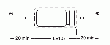
I went back and took another look at your photo of the underside of your amp. You definitely have one of the bias supply capacitors (the black Sprague Atoms) in backwards. One end of the cap is smooth, and the other end has a crimp around the circumference. The crimped end is the positive end of the cap. The cap connected directly to the bias pot must have the negative end attached to the center lug of the bias pot. The other cap must have the negative end attached to the non-banded side of the diode. Both caps must have their positive ends connected to ground.
You also need to make sure the bias rectifier diode is installed the correct way. Connect the banded end of the diode to the red/black lead off the power transformer. Those bias caps are polarized. Applying voltage to them in the wrong polarity can damage them.

You also need to make sure the bias rectifier diode is installed the correct way. Connect the banded end of the diode to the red/black lead off the power transformer. Those bias caps are polarized. Applying voltage to them in the wrong polarity can damage them.

-

Ty_Bower - KT88
- Posts: 1494
- Joined: Wed Mar 21, 2007 2:50 pm
- Location: Newark, DE
FATMAN wrote:Just noticed looking at the pictures that the cap on the 4 way terminal lug is positive to ground is this a non polerizied cap? or do I have the cap wrong?
It appears from the photo you have that one correct. It is the one attached to the bias pot that is in wrong. Though I can't imagine how that would result in a positive voltage showing up on the bias supply...?
-

Ty_Bower - KT88
- Posts: 1494
- Joined: Wed Mar 21, 2007 2:50 pm
- Location: Newark, DE
64 posts
• Page 3 of 5 • 1, 2, 3, 4, 5
Who is online
Users browsing this forum: No registered users and 12 guests
