With the recent talk of Mark III builders, I had a spurt of inspiration yesterday. I managed to 70% wire up one of my Mk3 blocks.
I had a handful of 100 ohm carbon film resistors, which I had bought for the screen ballast, but someone recommended against using carbon film at this position (they can burn if wattages are exceeded). Instead I found some old 80 ohm and some 150 ohm carbon composition parts in my junk box. I opted for the 80 ohm resistors.
The power wiring stupefies me. It's not that I can't figure out what to do - it's that the stock layout is so darn stupid. Between the hot and the neutral, they landed one on the fuse and the other on the switch. I think safety dictates the hot be attached directly to the fuse, but then the primary of the PT is connected to hot even when the power switch is turned off. I'm not real happy about that. There's no easy attachment lug nearby to hook it up right. I guess I'll need to leave a splice hanging in the wire somewhere.
I've basically got all the transformer leads landed somewhere, except for the C-354 and the B+ to the OT. Those will go to the SDS cap board, which is already assembled but not yet mounted. I put power to the thing just to check the bias circuit. I get an adjustment range of -42 volts to -67 volts. I expect this will be appropriate for the pair of KT88. While I had it powered up, I checked the AC voltage on the filament windings. I had heard that some Mark 3 owners had problems cause by excessively high line voltage. I measured 5.0 volts and 6.5 volts on the two windings. I’ve noted before that my digital AC meter might not be giving true RMS readings, so I’m going to have to borrow a Fluke or some other decent meter and check again. I stuck my old Radio Shack analog meter on the 5v winding and it looked like roughly 5.6 VAC.
After checking the heater windings, I summoned up the courage to stick the analog meter across the PT secondary. It measured just less than 900 VAC with no load. That’s some scary stuff. I wouldn’t want to get in between it and ground. In case anyone is interested, I also measured the DC resistance of the PT’s windings. The primary side is 1.6 ohms; the high voltage secondary is 82.5 ohms (end to end). This data might be useful if anyone wants to plug it into Duncan’s PSUDII.
I left my camera at the office, so no photos this time. Maybe I’ll get a few snapshots later. The next step is to cut a bunch of short jumpers and finish the wiring to the driver board. Then I've got to install the last cap for the bias supply, and hook up the SDS board.
A couple more questions: Concerning the 6.3V heater winding, I’ve landed the PT’s green leads on pins 2 and 7 of the closest KT88 socket. I need to run extensions to the second KT88, and then to the driver board. Does the phase of this wiring make any difference? I expect I’ll simply wire pin 2 on the first socket straight through to pin 2 on the second socket, but does it really make a difference one way or another? Is it crucial that the lead going to pin 2 end up on terminal E (and pin 7 on D) at the Poseidon board? I’m thinking strictly from a “hum” perspective here.
Finally, I hadn’t realized how half-assed the ground appears on the stock Mark 3. The power supply gets grounded at one of the triple lug terminal strips, the bias supply is hanging off the shell of the rectifier socket, the output tubes’ cathodes are grounded to a lug near the can cap, and the driver board is grounded who-knows where. Apparently, it was “good enough” to use the chassis as the ground plane. Any strong advice here? By the way, I ditched the can cap and my replacement tube sockets don’t have convenient grounding lugs, so I’m going to have to come up with something…
Good thing I don't build these for a living...
64 posts
• Page 1 of 5 • 1, 2, 3, 4, 5
Good thing I don't build these for a living...
![]() by Ty_Bower » Mon Oct 27, 2008 9:31 am
by Ty_Bower » Mon Oct 27, 2008 9:31 am
-

Ty_Bower - KT88
- Posts: 1494
- Joined: Wed Mar 21, 2007 2:50 pm
- Location: Newark, DE
![]() by FATMAN » Mon Oct 27, 2008 6:46 pm
by FATMAN » Mon Oct 27, 2008 6:46 pm
Hi I'm also building a MK3 from the parts available from triodelectronics and I am haveing some dificulty with the wiring with all the updated cap boards and posidon driver boards, Is there some sort of up dated schematic using these parts,I have the original Dynaco schematic and the posidon information but for somone with very little building experience (ME) I am afraid I will miss somthing, Any Ideas?
- FATMAN
- Posts: 36
- Joined: Sat Sep 30, 2006 9:12 am
- Location: Waterloo Ontario
![]() by Ty_Bower » Mon Oct 27, 2008 7:18 pm
by Ty_Bower » Mon Oct 27, 2008 7:18 pm
I'm using the Dynaco manual as my basic guide for the necessary connections and wiring layout. Of course, the wires leading to the Dynaco board need to go to the equivalent terminals on the Poseidon board (not too hard to figure out) and the wires attached to the can capacitor need to somehow end up on the (SDS?) cap board instead. I think the cap board is a little trickier, although not too much.
There's a very good hi-res colored .gif image of the stock wiring layout. It helps a lot with the basics. I think you'll find a copy around here somewhere:
http://www.diytube.com/phpBB2/viewtopic.php?t=1851
Jim built a pair of Mk3 last winter and posted some decent underside photos. His photo hosting site has since archived the images, but I saved a copy. I hope he doesn't mind me reposting them for him. By the way, if you're reading this Jim, I'd love to get a copy of your photos in high resolution.
You can find his original thread here:
http://www.diytube.com/phpBB2/viewtopic.php?t=2038


-
Ty_Bower - KT88
- Posts: 1494
- Joined: Wed Mar 21, 2007 2:50 pm
- Location: Newark, DE
![]() by FATMAN » Mon Oct 27, 2008 8:30 pm
by FATMAN » Mon Oct 27, 2008 8:30 pm
Ok thanks that is of some help, I can see I put my cap board the wrong way around, and the caps I was sent for the bias supply are 100mf that must be wrong too. Also I used the diodes in the cap board do I take the bias supply from that corner of the cap board beside the B+ ?
Thanks for your help. Also how can I post a picture?
Thanks for your help. Also how can I post a picture?
- FATMAN
- Posts: 36
- Joined: Sat Sep 30, 2006 9:12 am
- Location: Waterloo Ontario
![]() by Ty_Bower » Mon Oct 27, 2008 8:50 pm
by Ty_Bower » Mon Oct 27, 2008 8:50 pm
FATMAN wrote:Ok thanks that is of some help, I can see I put my cap board the wrong way around, and the caps I was sent for the bias supply are 100mf that must be wrong too. Also I used the diodes in the cap board do I take the bias supply from that corner of the cap board beside the B+ ?
Thanks for your help. Also how can I post a picture?
Cap board in the wrong way around is an easy fix.
The caps for the bias supply should be 100 uF, 100 V rated. In other words, you've got the right parts.
You can use diodes on the SDS board, but I'd stick with the 5AR4 rectifier. The peak inverse voltage across the rectifer will likely exceed 1.25 Kv, which is more than a UF4007 can handle. The P782 transformer has an awful lot of "ZOT!" in it.
DO NOT take the bias supply from the corner of the cap board. The bias supply needs to come from the 60 VAC winding off the PT. It should be color coded red/black.
I like Photobucket.com for hosting photos. Go to their site, sign up for a free account, and follow the directions for uploading photos. Check the box next to a photo and press the "Generate HTML" button at the bottom of the screen. Copy the text for "Image clickable thumbnails" and paste it into your posts.
-
Ty_Bower - KT88
- Posts: 1494
- Joined: Wed Mar 21, 2007 2:50 pm
- Location: Newark, DE
![]() by mesherm » Tue Oct 28, 2008 1:37 am
by mesherm » Tue Oct 28, 2008 1:37 am
A couple more questions: Concerning the 6.3V heater winding, I’ve landed the PT’s green leads on pins 2 and 7 of the closest KT88 socket. I need to run extensions to the second KT88, and then to the driver board. Does the phase of this wiring make any difference? I expect I’ll simply wire pin 2 on the first socket straight through to pin 2 on the second socket, but does it really make a difference one way or another? Is it crucial that the lead going to pin 2 end up on terminal E (and pin 7 on D) at the Poseidon board? I’m thinking strictly from a “hum” perspective here.
I always try to keep the filament lines on push pull pairs in phase with each other if possible. My thinking was that any filament hum would then be canceled out in the OT but I've never actually done any tests one way or the other.
Mike's N-1 Rule: When looking for N number of components to finish a job, you have a 95% chance of only finding N-1 of them.
-

mesherm - KT88
- Posts: 1232
- Joined: Fri Aug 27, 2004 10:33 pm
- Location: Alvin Texas
![]() by FATMAN » Tue Oct 28, 2008 4:48 am
by FATMAN » Tue Oct 28, 2008 4:48 am
Thanks again TY, I will remove the diodes from the SDS board I also have the BLK RED wire to that corner is that wrong too?. I am using the solid state plug in rectifier in place of the 5AR4 . I notice that the oposite side of the SDS board has lots of holes for grounding can I ground here as well as the 3 way terminal lug. Also in the Poseidon information they don't show a 680 ohm resitor across the out put from the 16 ohm tap to ground, what is that for? ....still lots more questions as I get through this if you don't mind. Thanks for all your help guys
Hope I can get some chokes from triodelectronics soon so I can complet this
Andrew
Hope I can get some chokes from triodelectronics soon so I can complet this
Andrew
- FATMAN
- Posts: 36
- Joined: Sat Sep 30, 2006 9:12 am
- Location: Waterloo Ontario
![]() by Ty_Bower » Tue Oct 28, 2008 9:08 am
by Ty_Bower » Tue Oct 28, 2008 9:08 am
FATMAN wrote:Thanks again TY, I will remove the diodes from the SDS board I also have the BLK RED wire to that corner is that wrong too? I am using the solid state plug in rectifier in place of the 5AR4. I notice that the opposite side of the SDS board has lots of holes for grounding can I ground here as well as the 3 way terminal lug. Also in the Poseidon information they don't show a 680 ohm resistor across the out put from the 16 ohm tap to ground, what is that for?
I believe the diodes you have should be used for the bias supply, not for the B+ supply. My SDS board did not come with diodes, if I recall correctly. And, unless they've changed something, the SDS board has no provisions for the bias supply filter.
Go follow the link in my post above to the hi-res colored pictorial that Bob Latino posted. It will show you where the red/black wire needs to go. On Bob's pictorial, it lands on a "selenium rectifier" located approximately in the center of the chassis. The selenium rectifier is prone to failure, and nobody puts them into the Mk3 any more. Instead, the 1N4007 or UF4007 diode should be used here. Jim’s photo shows it fairly well. If you look at his photo you can see where the diode is soldered across the outer lugs of a three terminal strip. The strip is bolted to the chassis where the selenium rectifier would have been. The banded end of the diode is the positive (+) end. That’s where the red/black wire gets connected. You can just barely see the red/black wire peeking out from underneath a ceramic disc capacitor on Jim’s amp. Next you’re going to ask about that ceramic disc cap – no, you didn’t get one with the Triode kit. It isn’t strictly necessary; it just reduces rectifier switching noise that might otherwise end up in the bias supply.
I hadn’t thought about using all those holes on the far side of the SDS board as a ground bus. I see no reason why it shouldn’t work fine, except getting it all soldered together will be tricky. The SDS board is designed in such a way that you need to do all the soldering from the underside. I don’t know why they didn’t use through-plated solder holes. Anyway, you’re going to need to flip the SDS board over to solder on the wires. If you solder stuff to both edges of the board, flipping it over is going to be very awkward.
There is a thread that discusses the purpose of the 680 ohm resistor. You should install it, as Shannon did all his stability testing with it in place. Shannon acknowledges he forgot to mention the resistor in the manual. I expect that Triode should have included them anyway.
http://www.diytube.com/phpBB2/viewtopic.php?t=1763
-
Ty_Bower - KT88
- Posts: 1494
- Joined: Wed Mar 21, 2007 2:50 pm
- Location: Newark, DE
![]() by TomMcNally » Tue Oct 28, 2008 1:31 pm
by TomMcNally » Tue Oct 28, 2008 1:31 pm
"I don’t know why they didn’t use through-plated solder holes."
With all due respect to Mr. SDS ... (I've used lots of his boards)
I think the answer to your question involves a kitchen table.
Yellow_Light_Colorz_PDT_08
... tom
With all due respect to Mr. SDS ... (I've used lots of his boards)
I think the answer to your question involves a kitchen table.
Yellow_Light_Colorz_PDT_08
... tom
-

TomMcNally - Darling du Jour
- Posts: 2729
- Joined: Sat Nov 19, 2005 2:19 pm
- Location: Northfield, NJ
![]() by FATMAN » Tue Oct 28, 2008 5:55 pm
by FATMAN » Tue Oct 28, 2008 5:55 pm
thanks Guy's, I got it mostly figured, you mention the .02 cap disk is this not the cap that they supply with the bias kit?, it looks different with gloss brown finish, I measued it as .02uf. I got the diode the right way with the white stipe on the red black PT wire. I will put the 680ohm across the 16 ohm out put terminal and ground. BTW the ground strip on the SDS board is great for all the grounds on that side,I left enough wire so it can be flipped. I will tidy it all up when it is all working.
When I wire up the KT88 tubes, the poseidon circut showes the terminals conecting the tubes though a 1K resistor from G and F to terminal 5 on the kt 88's also do I connect terminal 8 and 1 togeter and ground through the 10ohm resistor, and do I join 5 and 6 togeter for el34 tube's only?
Thanks for your help
Andrew
- FATMAN
- Posts: 36
- Joined: Sat Sep 30, 2006 9:12 am
- Location: Waterloo Ontario
![]() by Ty_Bower » Tue Oct 28, 2008 6:34 pm
by Ty_Bower » Tue Oct 28, 2008 6:34 pm
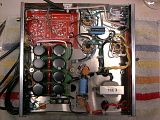
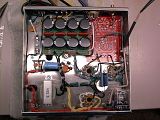
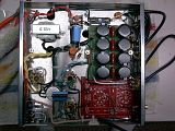
Dunno if this helps any, but here's some photos of my unfinished work:
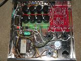
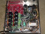
You can see the 0.02 uF disc cap on the 3-lug strip. It ties the 6.3V heater center tap (green/yellow) to ground. I wouldn't consider that cap part of the bias circuit. Did you get other ceramic disc caps in your kit?
Put the 1K ohm grid stopper resistors between pins 5 and 6. The resistor should be as close to pin 5 (grid) as reasonably possible. Pin 6 is not connected to anything inside the tube. It is just being used as a tie-in point, to hold the end of the resistor. Wire the Poseidon board to pin 6.
You might notice I also put 80 ohm resistors on pin 4 (screen). These act as "ballast" resistors to help prevent screen arc-overs, or so I've been told. I figure it's good insurance and can't hurt anything. You probably won't have these resistors in your kit.
You want to connect pins 8 and 1 together, and tie them to ground through a 10 ohm 1% precision metal film resistor. Do this regardless of whether you intend to use EL34 or KT88. The EL34 require it. The KT88 don't, but they aren't bothered by it being there.
-
Ty_Bower - KT88
- Posts: 1494
- Joined: Wed Mar 21, 2007 2:50 pm
- Location: Newark, DE
![]() by FATMAN » Wed Oct 29, 2008 5:26 am
by FATMAN » Wed Oct 29, 2008 5:26 am
thanks for the PICs, Nice I can enlarge the picture and see how it goes. I am just waiting for the chokes from triode electronics they are back ordered it there a hammond subsitute I can use untill they get stock?
can't wait to warm up the horns with 60watts!!
can't wait to warm up the horns with 60watts!!
- FATMAN
- Posts: 36
- Joined: Sat Sep 30, 2006 9:12 am
- Location: Waterloo Ontario
![]() by Ty_Bower » Wed Oct 29, 2008 7:33 am
by Ty_Bower » Wed Oct 29, 2008 7:33 am
I think the P-T156R is real close, although the DC voltage rating seems a little on the low side.
http://www.tubesandmore.com/scripts/fox ... em=P-T156R
http://www.tubesandmore.com/scripts/fox ... em=P-T156R
-
Ty_Bower - KT88
- Posts: 1494
- Joined: Wed Mar 21, 2007 2:50 pm
- Location: Newark, DE
![]() by FATMAN » Wed Oct 29, 2008 4:54 pm
by FATMAN » Wed Oct 29, 2008 4:54 pm
Thanks Ty , your amp is looking good! I will look up that choke How much voltage will there be? also I noticed that on the original MK3 they join both out put tubes together at PINs 1 and 8 are then joined to 1 and 8 on the second tube,then use a single 11.2 resitor to ground, I wired mine like in the poseidon schematic with pins 1 and 8 joined then through a 10 ohm 1/4 watt resistor to ground,and the same for the second KT88. is this a big enough resistor? 1/4 watt seems pretty light, I will add the other resistor that you added to pin 4 too, if you think it is nessesary.
Andrew
Andrew
- FATMAN
- Posts: 36
- Joined: Sat Sep 30, 2006 9:12 am
- Location: Waterloo Ontario
![]() by Ty_Bower » Wed Oct 29, 2008 8:09 pm
by Ty_Bower » Wed Oct 29, 2008 8:09 pm
The original Dynaco Mk3 has a shared bias circuit for the tube pair. Shannon's design improves upon this with an additional multi-turn trim pot located on the Poseidon board. This allows you to individually set the bias for each output tube. In order that you can measure each tube's idle current, separate cathode sense resistors must be installed.
1/4 watt is plenty. Each tube should draw 70 mA at idle. Across a 10 ohm resistor, you will see a 0.7 volt drop (V=I*R). Power dissipated in the resistor will be only 0.05 watt (P=I*V). If my math is right, the maximum current through the tube should be no more than 186 mA during impossibly loud peaks. Even at that current you'll only burn 0.35 watt in the cathode resistor.
The idea behind the cathode resistors' size is that it will act as a fusible link. If you are continuously running more than 1/4 watt through that resistor, something has gone wrong. Hopefully the resistor will burn out before your expensive output transformer does.
I couldn't say if the screen ballast resistor is necessary. Obviously, Dynaco felt it wasn't required. Then again, I disagree with several of their other design decisions, such as the usage of 525 volt rated power supply capacitors. Many people suggest the screen resistor is a prudent addition, which could potentially extend the life of the output tubes. I have only read one negative remark concerning the screen resistor; it suggested the amp sounded better without it. If I can find the article that promotes the concept, I'll post it here.
Edit - Here it is: http://www.audioxpress.com/magsdirx/ax/ ... ie2544.pdf
Look at the part starting on page 3 under the heading "Simple Solution".
Forgot to answer your first question. My P782 makes just under 900VCT with no load. If you've got a solid state plug in rectifier which you intend to use, the DC rail coming off the rectifier could be as much as sqrt(2)*900/2, or 635 volts.
-
Ty_Bower - KT88
- Posts: 1494
- Joined: Wed Mar 21, 2007 2:50 pm
- Location: Newark, DE
64 posts
• Page 1 of 5 • 1, 2, 3, 4, 5
Who is online
Users browsing this forum: No registered users and 4 guests