1.) Besides the SDS, a replacement cap, or PS from Curcio, what other options are there to rebuilding the Mark III power supply if you had all the room in the world under the chassis?
2.) If the SDS was the way to go, are there better caps for it and where can I get them? If not which Panasonic series should I get?
Power supply options
22 posts
• Page 1 of 2 • 1, 2
Power supply options
![]() by JW34 » Mon Feb 04, 2008 4:59 pm
by JW34 » Mon Feb 04, 2008 4:59 pm
- JW34
- Posts: 106
- Joined: Fri Feb 01, 2008 5:30 pm
- Location: Chicagoland
![]() by SDS-PAGE » Mon Feb 04, 2008 7:04 pm
by SDS-PAGE » Mon Feb 04, 2008 7:04 pm
Maybe oil caps or any of non-electrolytic caps if you have enough room for them? Whatever you do, make sure that they can handle minium of 630VDC. The insufficient voltage rating on the orginal cap was the very reason why people started making upgrade boards. I am running mine with 5U4 and 525VDC cap, and it's been trouble free. I am relying on the fact that 5U4 drops more volt than GZ34.
BTW, you can also buy 550VDC (600VDC surge) can caps at Dynakitparts.com.
BTW, you can also buy 550VDC (600VDC surge) can caps at Dynakitparts.com.
-

SDS-PAGE - KT88
- Posts: 865
- Joined: Thu Feb 22, 2007 4:41 pm
- Location: Brandon, SD
![]() by kheper » Tue Feb 05, 2008 1:47 am
by kheper » Tue Feb 05, 2008 1:47 am
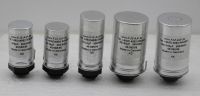
FT makes electrolytic caps rated 550/600V.
They are screw locks, not twist locks.
I cannot find a US supplier for these caps.
See below.
http://www.die-wuestens.de/eindex.htm
http://www.die-wuestens.de/pics/tn_550V.jpg
They are screw locks, not twist locks.
I cannot find a US supplier for these caps.
See below.
http://www.die-wuestens.de/eindex.htm
http://www.die-wuestens.de/pics/tn_550V.jpg
-

kheper - KT88
- Posts: 1252
- Joined: Wed Dec 21, 2005 10:14 pm
- Location: Philly, PA
![]() by crispycircuit » Tue Feb 05, 2008 12:23 pm
by crispycircuit » Tue Feb 05, 2008 12:23 pm
Thanks for the info... I never saw these! This is a cool find and I'm sure some one will pick up distribution of these... I HOPE????
- crispycircuit
- Posts: 104
- Joined: Tue Mar 20, 2007 9:32 pm
![]() by kheper » Wed Feb 06, 2008 12:23 am
by kheper » Wed Feb 06, 2008 12:23 am
This is a cool find and I'm sure some one will pick up distribution of these... I HOPE????
These can be ordered from this company by
paypal. You need to e-mail the person, ask
what the final price is, and pay in euros.
-
kheper - KT88
- Posts: 1252
- Joined: Wed Dec 21, 2005 10:14 pm
- Location: Philly, PA
Re: Power supply options
![]() by JW34 » Wed Feb 06, 2008 5:01 am
by JW34 » Wed Feb 06, 2008 5:01 am
JW34 wrote:1.) Besides the SDS, a replacement cap, or PS from Curcio, what other options are there to rebuilding the Mark III power supply if you had all the room in the world under the chassis?
2.) If the SDS was the way to go, are there better caps for it and where can I get them? If not which Panasonic series should I get?
I'm sorry, when I said replacement cap, I meant can. So besides a can, SDS and Cucio, how have others built their PS.
I know you can only use up to 50 uf on the first section, but does the voltage matter, meaning can you go beyond 600VDC...700VDC....1000 VDC without having to change any of the values on the driver board.
What about the other sections? Is there an unlimited amount of uf and VDC you can use without effecting the driver board?
Thanks,
Jay
Last edited by JW34 on Wed Feb 06, 2008 4:22 pm, edited 2 times in total.
- JW34
- Posts: 106
- Joined: Fri Feb 01, 2008 5:30 pm
- Location: Chicagoland
![]() by erichayes » Wed Feb 06, 2008 3:55 pm
by erichayes » Wed Feb 06, 2008 3:55 pm
F&T has limited distribution in the US through Antique Electronic Supply. Maybe if enough people bugged them, they'd expand the line. Just a thought . . .
Eric in the Jefferson State
- erichayes
- KT88
- Posts: 987
- Joined: Fri Jan 23, 2004 9:01 pm
- Location: McKinleyville CA
![]() by kheper » Thu Feb 07, 2008 3:36 am
by kheper » Thu Feb 07, 2008 3:36 am
I know you can only use up to 50 uf on the first section, but does the voltage matter, meaning can you go beyond 600VDC...700VDC....1000 VDC without having to change any of the values on the driver board.
I do not know what you mean by 'the
voltage'. The working voltage rating of the
cap?
The VDC rating of the cap should be, no
less than, 50V higher than the measured
voltage running thru it.
What about the other sections? Is there an unlimited amount of uf and VDC you can use without effecting the driver board?
There is a diminishing returns on upping the
uf in the later sections. With a solid state
rectifier a 100-100-100-100 series is pretty
cool.
With a tube rectifier 50-100-100-100 would
be a good choice. But it depends on which
caps you choose and how many can
physically fit into or on top of the amp.
Space is usually very limited.
-
kheper - KT88
- Posts: 1252
- Joined: Wed Dec 21, 2005 10:14 pm
- Location: Philly, PA
Re: Power supply options
![]() by Ty_Bower » Thu Feb 07, 2008 7:13 am
by Ty_Bower » Thu Feb 07, 2008 7:13 am
JW34 wrote:I know you can only use up to 50 uf on the first section, but does the voltage matter, meaning can you go beyond 600VDC...700VDC....1000 VDC without having to change any of the values on the driver board.
The voltage rating of the power supply capacitor only "matters" in the sense that it must be rated higher than the working voltages in the supply. If you try to put 600 volts on a capacitor rated for 500 it will leak, burn, or explode.
You may safely use a capacitor with a voltage rating higher than the original part. It will not affect the rest of the circuit.
The capacitance (often expressed in units of uF) of it may affect the rest of the circuit. Too large of a cap right after a tube rectifier can shorten the life of the rectifier.
-

Ty_Bower - KT88
- Posts: 1494
- Joined: Wed Mar 21, 2007 2:50 pm
- Location: Newark, DE
![]() by JW34 » Thu Feb 07, 2008 5:50 pm
by JW34 » Thu Feb 07, 2008 5:50 pm
So how about this:
One of these for the first section.
Two in parallel for the second section.
Two in parallel for the third.
Two in pasllel for the fourth.
http://www.die-wuestens.de/kd/KON5650.pdf
Would this work? Any modifications to the values on the Posiden? Would this be a big improvement?
Thanks for the responses,
Jay
- JW34
- Posts: 106
- Joined: Fri Feb 01, 2008 5:30 pm
- Location: Chicagoland
![]() by kheper » Thu Feb 07, 2008 9:33 pm
by kheper » Thu Feb 07, 2008 9:33 pm
So how about this:
One of these for the first section.
Two in parallel for the second section.
Two in parallel for the third.
Two in pasllel for the fourth.
You must have a chassis the size of Wisconsin.
FT makes 100uf caps and 100uf multi-caps.
-
kheper - KT88
- Posts: 1252
- Joined: Wed Dec 21, 2005 10:14 pm
- Location: Philly, PA
![]() by kheper » Wed Feb 20, 2008 12:14 am
by kheper » Wed Feb 20, 2008 12:14 am
The minimum (recommended) capacitance
in the power supply for a 55 Watt stereo
amp with a 480V B+, like the MKIII is:
Watts = 55W x 2 = 110W
E = 480Vdc
C = total power supply capacitance
W = 110
E = 480
C = 110 / 480 x 480
C = 110 / 230400
C = .00048 F
C = 480 uf
Look at the multi-cap lug #3 in the MKIII
manual. The voltage there is 330Vdc. You
might get away with a JJ 220uf 385Vdc
electrolytic, like the one pictured here:
http://us.st11.yimg.com/us.st.yimg.com/ ... 6_19305451
JJ also makes a 330uf and 550uf in this
series. Might be worth looking into.
If you have not yet decided on a power
tranny and were going solid-state on the
rectifier, but feared that the resulting
voltage could touch the ratings of the
capacitors, you could make a hybrid
solid-state/tube full-wave bridge rectifier.
http://homepages.ihug.co.nz/~rwillis/al ... ifier.html
With this configuration, you get a nice
voltage drop and a delayed turn on. No
real necessity for a slow start mechanism.
A 350@425ma non-center tap supply
should be about right.
-
kheper - KT88
- Posts: 1252
- Joined: Wed Dec 21, 2005 10:14 pm
- Location: Philly, PA
![]() by Ty_Bower » Wed Feb 20, 2008 8:00 am
by Ty_Bower » Wed Feb 20, 2008 8:00 am
kheper wrote:Look at the multi-cap lug #3 in the MKIII
manual. The voltage there is 330Vdc. You
might get away with a JJ 220uf 385Vdc
electrolytic...
The voltage is only 330v as long as:
- lug #4 is at 430v
- V1 is drawing 1mA across R16
If you pull V1, then the voltage at lug #3 is going to charge up to whatever you've got at lug #4. If you pull V2, then the voltage at both lug #3 and #4 is going to end up higher. If you pull the output tubes, then all the voltages are going to end up much higher than otherwise expected.
The power supply caps in the original MkIII were spec'd to be right on the edge. If you ran it with the GZ34 in and the KT88 out, you were guaranteed to blow the can cap. If you're going to the trouble to rebuild the power supply, you may as well use some caps that can handle any voltage the transformer can put out, even in the event that a tube fails and stop conducting.
-
Ty_Bower - KT88
- Posts: 1494
- Joined: Wed Mar 21, 2007 2:50 pm
- Location: Newark, DE
![]() by kheper » Wed Feb 20, 2008 9:15 am
by kheper » Wed Feb 20, 2008 9:15 am
The voltage is only 330v as long as:
- lug #4 is at 430v
- V1 is drawing 1mA across R16
Correct. My error.
It is best to stay with the 550V multi-caps or
use a cap-board. Too bad those FT caps
do not have higher than 100uf.
You could also series the high capacitance JJ
385V caps.
-
kheper - KT88
- Posts: 1252
- Joined: Wed Dec 21, 2005 10:14 pm
- Location: Philly, PA
22 posts
• Page 1 of 2 • 1, 2
Who is online
Users browsing this forum: No registered users and 9 guests