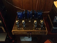
I am almost finished with my first Mark III monoblock. All that is left to do is to wire the status L.E.D. and check all wiring and all test readings. This is the first pic of many more to follow. The status L.E.D. will blink red while the heaters do there thing and then after a few moments, The high voltage kicks in and the status L.E.D. turns green. I will be installing this L.E.D. in the center of the preamp socket in front of the chasis. I seen this idea somewhere on this forum.
http://hilldwellerstl.myphotoalbum.com/ ... me=album03 :) :) :)
New Build Mark III's One down and one to go! 1st. Pic.
24 posts
• Page 1 of 2 • 1, 2
New Build Mark III's One down and one to go! 1st. Pic.
![]() by hilldweller » Thu Dec 06, 2007 7:26 pm
by hilldweller » Thu Dec 06, 2007 7:26 pm
Analog is Real! Experience it!
Digital leads to trans humanism. Not good.
Digital leads to trans humanism. Not good.
-
hilldweller - KT88
- Posts: 285
- Joined: Wed Aug 01, 2007 5:28 pm
- Location: St. Louis Missouri USA
![]() by TomMcNally » Thu Dec 06, 2007 8:10 pm
by TomMcNally » Thu Dec 06, 2007 8:10 pm
Very nice job !
Is that a Velleman time delay relay board ?
Is that a Velleman time delay relay board ?
-

TomMcNally - Darling du Jour
- Posts: 2729
- Joined: Sat Nov 19, 2005 2:19 pm
- Location: Northfield, NJ
![]() by hilldweller » Thu Dec 06, 2007 8:14 pm
by hilldweller » Thu Dec 06, 2007 8:14 pm
TomMcNally wrote:Very nice job !
Is that a Velleman time delay relay board ?
No, I got them on Ebay For $15.00 Ea. See Link.
http://cgi.ebay.com/Power-Supply-Delay- ... dZViewItem
Analog is Real! Experience it!
Digital leads to trans humanism. Not good.
Digital leads to trans humanism. Not good.
-
hilldweller - KT88
- Posts: 285
- Joined: Wed Aug 01, 2007 5:28 pm
- Location: St. Louis Missouri USA
![]() by hilldweller » Thu Dec 06, 2007 8:25 pm
by hilldweller » Thu Dec 06, 2007 8:25 pm
TomMcNally wrote:Very nice job !
Is that a Velleman time delay relay board ?
NO!
Please note that this board does not come with the bi-color led setup. This is one of my mods. I got the bi-color leds from Parts Express. The board comes with two red leds but the blinking one is covered up by heatshrink tubing and only the plate voltage one is exposed. I replaced this setup with the bi-color leds myself. Yellow_Light_Colorz_PDT_12
Analog is Real! Experience it!
Digital leads to trans humanism. Not good.
Digital leads to trans humanism. Not good.
-
hilldweller - KT88
- Posts: 285
- Joined: Wed Aug 01, 2007 5:28 pm
- Location: St. Louis Missouri USA
![]() by TomMcNally » Thu Dec 06, 2007 8:46 pm
by TomMcNally » Thu Dec 06, 2007 8:46 pm
I was just wondering about the delay board.
I see Washington Audio has the Studer/Revox B225
CD player on eBay for $ 599.99 ...
I had one of those under my desk at work and I think
I finally played Dumpster Toss with it. grrrr

I see Washington Audio has the Studer/Revox B225
CD player on eBay for $ 599.99 ...
I had one of those under my desk at work and I think
I finally played Dumpster Toss with it. grrrr
-
TomMcNally - Darling du Jour
- Posts: 2729
- Joined: Sat Nov 19, 2005 2:19 pm
- Location: Northfield, NJ
Washington Audio & Revox Plinker?
![]() by hilldweller » Thu Dec 06, 2007 9:24 pm
by hilldweller » Thu Dec 06, 2007 9:24 pm
I do not know much about Washington Audio, But I can tell you that these delay boards do just what there supposed to do. I have tested them thoroughly. The timing is perfect for this amp. It looks to be a pretty reliable and straight forward design, However, I would reccomend mounting them in the coolest corner of your chassis config. Durability has yet to bee seen but for 15 bucks, what the hay?
Revox,
I didn't know they made a CD player. I know they made excellent tape machines, and some hyped up tuners. Nice to know.
Revox,
I didn't know they made a CD player. I know they made excellent tape machines, and some hyped up tuners. Nice to know.
Analog is Real! Experience it!
Digital leads to trans humanism. Not good.
Digital leads to trans humanism. Not good.
-
hilldweller - KT88
- Posts: 285
- Joined: Wed Aug 01, 2007 5:28 pm
- Location: St. Louis Missouri USA
![]() by Ty_Bower » Wed Dec 12, 2007 6:05 pm
by Ty_Bower » Wed Dec 12, 2007 6:05 pm
A very fine looking build, if I may say so. I wish I could get mine to that stage. I'm trying to build nearly the same amps (SDS cap board, Poseidon driver) the difference being mine are on original Dynaco chassis and iron. I also seem to lack enough time to finish the wiring.
Let us know how it turns out. I'm particularly interested in your choice of AF and PI tubes. Your photos suggest a 12AX7 and a 12AU7. I'm hoping to run a 5751 and a 12BH7 in mine, built per Ned's schematic.
And where'd you get those plugs to fill the can cap hole?
Let us know how it turns out. I'm particularly interested in your choice of AF and PI tubes. Your photos suggest a 12AX7 and a 12AU7. I'm hoping to run a 5751 and a 12BH7 in mine, built per Ned's schematic.
And where'd you get those plugs to fill the can cap hole?
-

Ty_Bower - KT88
- Posts: 1494
- Joined: Wed Mar 21, 2007 2:50 pm
- Location: Newark, DE
![]() by hilldweller » Wed Dec 12, 2007 8:38 pm
by hilldweller » Wed Dec 12, 2007 8:38 pm
Ty_Bower wrote:A very fine looking build, if I may say so. I wish I could get mine to that stage. I'm trying to build nearly the same amps (SDS cap board, Poseidon driver) the difference being mine are on original Dynaco chassis and iron. I also seem to lack enough time to finish the wiring.
Let us know how it turns out. I'm particularly interested in your choice of AF and PI tubes. Your photos suggest a 12AX7 and a 12AU7. I'm hoping to run a 5751 and a 12BH7 in mine, built per Ned's schematic.
And where'd you get those plugs to fill the can cap hole?
I got the chrome plug from my local hardware store. The 12AU7 is actually a JJ ECC802-S which is specifically designed for audio use. It has a long plate structure and has low noise and microphonics. See link:
http://store.triodestore.com/jjec12lopl.html
Is your choice for using 5751 & 12BH7 for a particular reason, such as higher gain??? Let me know. I may try 12AT7. I am in the progress of building my second MK-III. When the second one is done, I will hook them up and see how they sound. I will be driving them with the Grounded Grid Preamp offered by Transcendent Sound. This preamp has had great reviews from around the world. See Link:
http://www.transcendentsound.com/preampkit.htm
If you can tell me why you wish to use the Ned tube set-up, I would really like to know. Thanks for you interest! Yellow_Light_Colorz_PDT_12
Analog is Real! Experience it!
Digital leads to trans humanism. Not good.
Digital leads to trans humanism. Not good.
-
hilldweller - KT88
- Posts: 285
- Joined: Wed Aug 01, 2007 5:28 pm
- Location: St. Louis Missouri USA
![]() by Ty_Bower » Thu Dec 13, 2007 5:06 am
by Ty_Bower » Thu Dec 13, 2007 5:06 am
hilldweller wrote:Is your choice for using 5751 & 12BH7 for a particular reason, such as higher gain???
[snip]
If you can tell me why you wish to use the Ned tube set-up, I would really like to know. Thanks for you interest! Yellow_Light_Colorz_PDT_12
Well, I happen to have a few spare 5751 and 12BH7 around. There's talk in the ST35 forum how some people prefer those tubes in the ST35 (although I will grant the Poseidon and the ST35 don't have the same kind of phase splitter.) Finally, the Ned version of the Poseidon schematic suggests using the 5751 and the 12BH7.
I'm using Ned's setup because I bought the blank boards from his shop. His eBay price seemed about right, and he offered the convenience of including all the required parts in the kit. There's a copy of his version of the schematic somewhere in one of the stickied posts. He only changed a couple of the component values, presumably to move the lines slightly more in favor of the tubes he recommends.
-
Ty_Bower - KT88
- Posts: 1494
- Joined: Wed Mar 21, 2007 2:50 pm
- Location: Newark, DE
![]() by Slartibartfast » Thu Dec 13, 2007 3:55 pm
by Slartibartfast » Thu Dec 13, 2007 3:55 pm
hilldweller wrote:TomMcNally wrote:Very nice job !
Is that a Velleman time delay relay board ?
No, I got them on Ebay For $15.00 Ea. See Link.
http://cgi.ebay.com/Power-Supply-Delay- ... dZViewItem
Where did you add this to the circuit. I would like to add one of these to my ST 70, but his directions were not to clear.
Thanks,
Robert
-

Slartibartfast - KT88
- Posts: 458
- Joined: Sun Apr 15, 2007 9:40 pm
- Location: Columbia S.C.
Delay circuit hookup
![]() by hilldweller » Thu Dec 13, 2007 5:47 pm
by hilldweller » Thu Dec 13, 2007 5:47 pm
Slartibartfast wrote:hilldweller wrote:TomMcNally wrote:Very nice job !
Is that a Velleman time delay relay board ?
No, I got them on Ebay For $15.00 Ea. See Link.
http://cgi.ebay.com/Power-Supply-Delay- ... dZViewItem
Where did you add this to the circuit. I would like to add one of these to my ST 70, but his directions were not to clear.
Thanks,
Robert
The small twisted pair of green wires go to the 6.3 vac filament supply, you can tap in to the filament wires at the closest tube socket in parallel. This is what powers the delay board. The two sets of red & blue twisted pair wires go to the high voltage supply off of the power transformer. On the ST-70, you would hook each twisted pair off of the delay board in series with the red transformer wires on the PA060 power transformer. You could use one set of these wires and hook it in series with one of the high voltage transformer wires, Or you can do as I did and hook each pair in series with the two high voltage leads off of the transformer. than when you power up the amp, The filaments will come on first and than after about 20 seconds or so, the relay kicks in and turns on the plate voltage. If this helps, Great! If not, I can make a schematic for you. :)
Analog is Real! Experience it!
Digital leads to trans humanism. Not good.
Digital leads to trans humanism. Not good.
-
hilldweller - KT88
- Posts: 285
- Joined: Wed Aug 01, 2007 5:28 pm
- Location: St. Louis Missouri USA
![]() by Ty_Bower » Wed Jan 02, 2008 5:45 pm
by Ty_Bower » Wed Jan 02, 2008 5:45 pm
I'm staring at your under-chassis wiring photos. I see what looks like four ceramic disc capacitors. Two near the power cord (off ground and neutral?), one across the diode for the bias supply, and one from the yellow-striped green wire (heater center tap) to ground.
Any comments? I think only the last one appears in the original Dynaco schematic.
Any comments? I think only the last one appears in the original Dynaco schematic.
-
Ty_Bower - KT88
- Posts: 1494
- Joined: Wed Mar 21, 2007 2:50 pm
- Location: Newark, DE
Extra Caps you seen
![]() by hilldweller » Wed Jan 02, 2008 6:54 pm
by hilldweller » Wed Jan 02, 2008 6:54 pm
Ty_Bower wrote:I'm staring at your under-chassis wiring photos. I see what looks like four ceramic disc capacitors. Two near the power cord (off ground and neutral?), one across the diode for the bias supply, and one from the yellow-striped green wire (heater center tap) to ground.
Any comments? I think only the last one appears in the original Dynaco schematic.
The caps you seen at the power cord inlet ar X / Y Ceramic disc caps. The purpose of these is for eliminating line hum and for eliminating possible shocks when touching the chassis. The one bypasing the diode help eliminate noise from digital sources. See link,
http://home.netcarrier.com/~rstevens/mk-III.html
Yellow_Light_Colorz_PDT_11
Analog is Real! Experience it!
Digital leads to trans humanism. Not good.
Digital leads to trans humanism. Not good.
-
hilldweller - KT88
- Posts: 285
- Joined: Wed Aug 01, 2007 5:28 pm
- Location: St. Louis Missouri USA
P.S. Also notice the 100 ohm screen resistors
![]() by hilldweller » Wed Jan 02, 2008 7:06 pm
by hilldweller » Wed Jan 02, 2008 7:06 pm
Ty_Bower wrote:I'm staring at your under-chassis wiring photos. I see what looks like four ceramic disc capacitors. Two near the power cord (off ground and neutral?), one across the diode for the bias supply, and one from the yellow-striped green wire (heater center tap) to ground.
Any comments? I think only the last one appears in the original Dynaco schematic.
Screen resistor to protect the $$$ KT-88s
Eliminates screen instabilities. I found this somewhere on this forum. Yellow_Light_Colorz_PDT_12
Analog is Real! Experience it!
Digital leads to trans humanism. Not good.
Digital leads to trans humanism. Not good.
-
hilldweller - KT88
- Posts: 285
- Joined: Wed Aug 01, 2007 5:28 pm
- Location: St. Louis Missouri USA
Re: P.S. Also notice the 100 ohm screen resistors
![]() by Ty_Bower » Wed Jan 02, 2008 7:30 pm
by Ty_Bower » Wed Jan 02, 2008 7:30 pm
hilldweller wrote:Screen resistor to protect the $$$ KT-88s
Eliminates screen instabilities. I found this somewhere on this forum. Yellow_Light_Colorz_PDT_12
I think this might be the one. What size did you use? 100 ohm?
http://www.diytube.com/phpBB2/viewtopic.php?t=1455
-
Ty_Bower - KT88
- Posts: 1494
- Joined: Wed Mar 21, 2007 2:50 pm
- Location: Newark, DE
24 posts
• Page 1 of 2 • 1, 2
Who is online
Users browsing this forum: No registered users and 10 guests