Page 1 of 1
A-430 OPT's Secondaries Strapping

Posted:
Sat Sep 15, 2007 9:30 pmby SDS-PAGE
I strapped 16 ohms secondary on my A-430 OPT to common with a 680 ohms resistor as per schematic of MKIII. The MKII schematic calls for strapping 16 ohms - common by 0.1 uF in series with 47 ohms. Am I OK with 680 ohms? What's the purpose of the strapping? Thanks. -Min
Posted:
Sun Sep 16, 2007 12:19 amby erichayes
The 680Ω resistor has been popularly thought to be a safety device to keep a load on the OT in case of speakers or other loads not being connected. I've never bought in to this theory, as 470Ω is way to high to offer any real protection. My gut feeling was that it was a snubber to suppress high frequency ringing.
I've never given close scrutiny to the MK-II circuit, but if what you say is hanging across the secondary is factual, that reenforces my feeling. Usually, snubbers are put on the primary of the OT, between the plates, I guess there's no reason it can't be done on the secondary--just a little less efficient.
In any event, I'd go with the 680Ω for starters, and , if you have access to a scope and a 1000~ square wave source, take a look at the output waveform. If you don't, give me a call and I'll see what we can work out.
Posted:
Sun Sep 16, 2007 5:44 amby Shannon Parks
I second what Eric is saying. It is some of 'zobel network' - forgive the term in this application. I used a cap and a ten ohm resistor in the Ikes.
The witchcraft/majick art of amp stability is trial and error for me, and even the most educated calculation (or simulation these days) would be followed up with simple bench tests. I use a 10kHz square wave with a 8 ohm resistive load, then with a .22uF capacitive load, then with no load. Be ready to attenuate your function generator if - I mean when - the amp goes unstable.
Posted:
Sun Sep 16, 2007 3:25 pmby SDS-PAGE
Thanks, Eric and Shannon for your input. I don't have a scope, so I can't do these tests. Maybe, I can look up someone at electric engineering or physics department here at UC Davis for one. Most of my network is in bio sci. Thanks, Eric for your offer. I will let you know when I need your assistance. -Min
Posted:
Sun Sep 16, 2007 4:26 pmby TomMcNally
Slightly off topic - but funny.
I had a 10,000 watt FM transmitter that was blowing
rectifier stacks, which were series connected boards
with about 16 diodes on them. The manufacturer
sent me a "snubber" which was a foot long phenolic
board with a big 100 watt resistor and a six inch long
half inch diameter glass oil filled capacitor.
This went across the secondary of the 4000 volt
power transformer. A few weeks later the thing
kicked off, and when I opened it, there was oil
all over everything ... the capacitor blew apart
and so did the resistor. The transmitter has been
a mess ever since, with dust sticking to the oil,
which was basically impossible to clean off.
... tom
Posted:
Sun Sep 16, 2007 6:01 pmby erichayes
Be thankful it was oil and not PCB . . .
Posted:
Mon Sep 17, 2007 4:54 amby Shannon Parks
TomMcNally wrote:... the capacitor blew apart
and so did the resistor. The transmitter has been
a mess ever since, with dust sticking to the oil,
which was basically impossible to clean off.
My blown cap (with an oil NOS cap) was a scary experience, but getting my airlock bubbler jammed with hops in a 5 gallon carboy of homebrew was a huge mess. That laundry room at my old house will never be the same. Yellow_Light_Colorz_PDT_04
Posted:
Wed Oct 03, 2007 10:45 amby Ty_Bower
separks wrote:I second what Eric is saying. It is some of 'zobel network' - forgive the term in this application.
Back to the 680 ohm resistor on the Mark III schematic...
I'll assume the right thing to do is remove it if you are installing the Poseidon board? This resistor is only appropriate for the stock Mark III driver circuit, correct?
Posted:
Wed Oct 03, 2007 11:38 amby Shannon Parks
Hi Ty,
I did all my testing with it in there, so leave it. I do believe my schematic doesn't show it, though it is on the parts list. One more item I need to fix.
Posted:
Wed Oct 03, 2007 12:14 pmby EWBrown
I'd just leave it in place. That high of a resistance, 680 ohms vs 8 or 16 ohms impedance will have little detectable effect on the frequency response. We're talking on the order of millibels here Yellow_Light_Colorz_PDT_06
Probably served as a transient suppressor / snubber, or offered some minor protection against operating the amp with no load attached (NOT a good thing to do...)
/ed B in NH
Posted:
Wed Oct 03, 2007 12:20 pmby Ty_Bower
You're right, the Poseidon schematics do not show it.
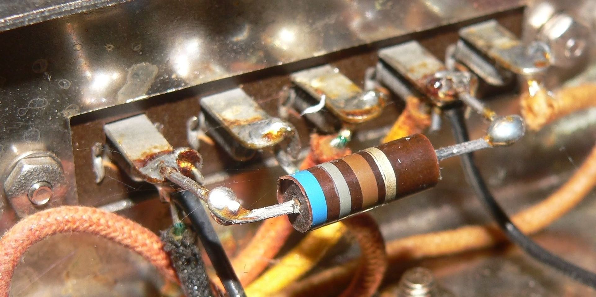
Guess I'm going to have to get a couple new 680 ohm resistors. This one looks like it's blown a chunk.