I've had a newly built Dynaco ST-35 for some time now and it's worked really nice, apart from a little hum in the left channel. I was able to squeeze in the Enhanced Fixed Bias as well. Everything is new.
Before I built this unit, I checked all resistors before and after to make sure the values were as advertised. Everything was spot on. I decided to check them the other day, along with voltage readings. Voltage readings were fine with the output tubes, but a little weird with the input tubes. All resistor readings were good except for the 300K (R5) in the left channel. It measured 390K whereas the right channel measured 300K. Not sure how the resistance increased after the amp was put in use, but I'll a get a new one tomorrow.
Voltage readings on the input tubes were (published specs to the right)
L R
PIN 1 - 246 VDC 230 VDC 215-230
PIN 2 - 90 VDC 113 VDC 112
PIN 3 - 113 VDC 128 VDC 116
PIN 4 - 6.0 VAC 6.0 VAC 6.3
PIN 5 - 6.0 VAC 6.0 VAC 6.3
PIN 6 - 96 VDC 115 VDC 112
PIN 7 - 0 0 0
PIN 8 - 0.73 VDC 0.90 VDC 0.85
PIN 9 - same as pins 4&5
The right channel figures are good except for PIN 3 (cathode) which seems too high. Not sure why this is. Any thoughts?
Left channel PIN 3 is very good however, but the other readings may come on with replacing the R5 resistor maybe?
Any insight into this "problem" would be appreciated.
Dynaco ST-35 voltage readings
27 posts
• Page 1 of 2 • 1, 2
Dynaco ST-35 voltage readings
![]() by Stunch » Tue Jul 03, 2012 10:17 am
by Stunch » Tue Jul 03, 2012 10:17 am
- Stunch
- Posts: 55
- Joined: Fri Feb 04, 2011 3:50 pm

![]() by paart » Thu Jul 05, 2012 8:27 pm
by paart » Thu Jul 05, 2012 8:27 pm
Stunch
You have an issue that might be caused by R5 being the wrong value. After you replace this resistor, recheck all the same voltages, trying to be as precise as possible. Pin 2 and 6 should be wired together, and therefore have the same voltage appearing on each pin (to ground). You shouldn't see the amount of variation that you are listing. Take your time and double check your readings.
You have an issue that might be caused by R5 being the wrong value. After you replace this resistor, recheck all the same voltages, trying to be as precise as possible. Pin 2 and 6 should be wired together, and therefore have the same voltage appearing on each pin (to ground). You shouldn't see the amount of variation that you are listing. Take your time and double check your readings.
- paart
- Posts: 95
- Joined: Mon Jul 17, 2006 8:36 pm
- Location: Central PA
![]() by Ty_Bower » Fri Jul 06, 2012 6:32 am
by Ty_Bower » Fri Jul 06, 2012 6:32 am
Just for the record, this is a genuine Dynaco Stereo 35, and not Shannon's DIY ST35. You've got a 12DW7 tube for each channel.
Pins 6, 7, and 8 are the plate, grid, and cathode (respectively) for the AF amp portion of the driver stage. The grid must be at zero volts, as it is on both channels of your amp. That is good. The bias on this section should be effectively determined by the value of the 1.3k resistor connected to pin 8 (cathode). Current flowing through the section will cause a voltage drop across Rk, and that voltage (positive with respect to the grid) sets the bias. Using Ohm's law and the cathode voltages you reported, the idle current through the AF amp would be 0.56 mA on the left channel, and 0.69 mA on the right. This is reasonable for a section with characteristics roughly similar to the 12AX7.
Pin 6 is the plate of this section. The current that flows through the tube must also flow through the plate load resistor (which should be 300k). Again using Ohm's law one can calculate that 0.69 mA through the 300k resisor should present a 208V drop. If you add that drop to the plate voltage, 208V + 115V = 323V, you should get the front end power supply voltage. You can verify this by measuring at the junction between the 6.8k resistor and the 20uF cap in the power supply.
Repeat the above exercise for the left channel, but instead note the plate load resistor measured 390k. 0.56 mA current across 390k gives a 219 volt drop. 219V added to the measured plate voltage (96V) gives 315V at the front end supply. Something is slightly amiss here, as the front end supply voltage is common for both channels and should give the same results. We probably have a slight measurement error somewhere.
It is also worthwhile to note that since this plate load resistor is too high in value, it will drop more voltage than it should and result in too low of a plate voltage. This may cause problems in the next stage of the amp. At this point I would suggest replacing the "bad" 390k resistor with the proper value and recheck your voltages. If they still look funny, swap the 12DW7 between the left and right channels and check voltages again. Report back with your findings.
"It's a different experience; the noise occlusion, crisp, clear sound, and defined powerful bass. Strong bass does not corrupt the higher frequencies, giving a very different overall feel of the sound, one that is, in my opinion, quite unique."
-

Ty_Bower - KT88
- Posts: 1494
- Joined: Wed Mar 21, 2007 2:50 pm
- Location: Newark, DE
![]() by Stunch » Fri Jul 06, 2012 7:56 am
by Stunch » Fri Jul 06, 2012 7:56 am
Thanks Ty and Art for your responses. Yes pins 2 and 6 should be the same as they are tied together. I wrote down the reading from one day for pin 2, and then from another day for pin 6. The readings are/were identical when measured on the particular day though. I did measure the readings at the quad cap, and at the 20 uF I got 347 VDC. First stage was 415 VDC and B+ was 409 VDC. the voltage into the house is about 122V.
I swapped the 12DW7's and readings were almost identical. I'm picking up a couple of 300K resistors today along with a matched pair of 12DW7's. I'll hook up a thermistor as well to drop the voltage a little. The resistor should bring some of the suspect readings in line, but I still wonder about the cathode (pin 3) reading in the right channel being high, when all other readings look good. This is why I'm going to try a different brand of tubes.
I swapped the 12DW7's and readings were almost identical. I'm picking up a couple of 300K resistors today along with a matched pair of 12DW7's. I'll hook up a thermistor as well to drop the voltage a little. The resistor should bring some of the suspect readings in line, but I still wonder about the cathode (pin 3) reading in the right channel being high, when all other readings look good. This is why I'm going to try a different brand of tubes.
- Stunch
- Posts: 55
- Joined: Fri Feb 04, 2011 3:50 pm
![]() by paart » Fri Jul 06, 2012 8:45 am
by paart » Fri Jul 06, 2012 8:45 am
The bottom line, as far as the phase inverter, is that you are trying for a difference of 4 VDC between the cathode and the grid. The lower voltage, of course, should be at the grid, biasing it negative. Rather than showing a 4 volt differential, you have 23V on one channel, and 15V on the other.
For the grid voltage to be in range, the plate voltage on the prior stage must be correct, since it's directly coupled to the phase inverter grid. I'm curious about what you are using for 12DW7/7247 tubes. You mentioned that you have a matched pair, but are planning to try another brand. Could you supply some details about these tubes?
Yes, your B+ runs a little high due to your high AC line voltage. I'd let that go at this point, until you get the other issues resolved.
- paart
- Posts: 95
- Joined: Mon Jul 17, 2006 8:36 pm
- Location: Central PA
![]() by Stunch » Fri Jul 06, 2012 9:28 am
by Stunch » Fri Jul 06, 2012 9:28 am
I have a pair of JJ 12DW7's in the amp right now. I don't think they are matched, although I get similar readings when swapping them. I'm getting a matched pair of EH 12DW7's this afternoon form Parts Connexion (about an hour from here). I'll put in the new resistor and tubes and take some readings on the weekend.
It's interesting that the cathode on the inverter side (pin 3) on the left side is very good, when all the other readings are suspect, and the cathode on the right side is off, yet all the other readings are good.
It's interesting that the cathode on the inverter side (pin 3) on the left side is very good, when all the other readings are suspect, and the cathode on the right side is off, yet all the other readings are good.
- Stunch
- Posts: 55
- Joined: Fri Feb 04, 2011 3:50 pm
![]() by Ty_Bower » Fri Jul 06, 2012 1:45 pm
by Ty_Bower » Fri Jul 06, 2012 1:45 pm
So here's what's bugging me. If you look at the plate curves for the second section of 12DW7, they don't fit what Stunch has in his amp.
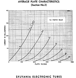
Here's a little table I made to help me figure things. Please, check my math as I am certain I've made a mistake in here somewhere.
(Left Channel)
B+ 347
Va 246
Vg 90
Vk 113
Vak 133
Vgk -23
Ia 3.74 mA
Ik 3.42 mA
(Right Channel)
B+ 347
Va 230
Vg 113
Vk 128
Vak 102
Vgk -15
Ia 4.33 mA
Ik 3.88 mA
(Factory Spec)
B+ 320
Va 215
Vg 112
Vk 116
Vak 106
Vgk -4
Ia 3.89 mA
Ik 3.52 mA
According to the plate curves, at the 102~133 volts from anode to cathode (Vak), we should always be greater than -5 volts grid-to-cathode (Vgk) with the current values we see here. Yet somehow, Stunch's tubes are in the -15 to -23 region. Those tubes should be well into cutoff considering the available potential from anode to cathode. Perhaps these JJ tubes are not very good replicas of the 12DW7?
I'm gonna go get my DIY ST-35 amps and get some measurements, because I'm curious now!
Last edited by Ty_Bower on Fri Jul 06, 2012 3:10 pm, edited 1 time in total.
"It's a different experience; the noise occlusion, crisp, clear sound, and defined powerful bass. Strong bass does not corrupt the higher frequencies, giving a very different overall feel of the sound, one that is, in my opinion, quite unique."
-
Ty_Bower - KT88
- Posts: 1494
- Joined: Wed Mar 21, 2007 2:50 pm
- Location: Newark, DE
![]() by Ty_Bower » Fri Jul 06, 2012 3:06 pm
by Ty_Bower » Fri Jul 06, 2012 3:06 pm
Ty_Bower wrote:I'm gonna go get my DIY ST-35 amps and get some measurements, because I'm curious now!
Must not be my lucky day. One of my digital meters is broken, one was left at work, the third is a pocket job that wont go past 200V and the last is AWOL. I had to use the trusty old analog meter. Hopefully I can keep the division straight and not read 10 v/div when it should be 5.
The line voltage was read as 116 VAC. This meter has a known history of reading "funny", as in never the same as any of my digital meters on the AC scales. I recall it typically gives lower numbers. 116 VAC seems awfully low for my neighborhood, but it is stinking hot outside. There are a lot of air conditioning units running today.
The iron complement is all original Dynaco. They were gutted from an SCA35. The board is Shannon's rev C. The 12AU7 phase inverter is an old Silvertone "Made in USA" marked tube - probably Sylvania or GE.
Front end B+ was 323 VDC. Plate voltage on both channels was 215 VDC. One side had 104V on the grid and 108V cathode. The other was 100V grid and 105V cathode.
In summary, Vgk was exactly what should be expected, as was Va. B+ was awfully close. I may go dig out the other DIY ST35 and see how it feels.
"It's a different experience; the noise occlusion, crisp, clear sound, and defined powerful bass. Strong bass does not corrupt the higher frequencies, giving a very different overall feel of the sound, one that is, in my opinion, quite unique."
-
Ty_Bower - KT88
- Posts: 1494
- Joined: Wed Mar 21, 2007 2:50 pm
- Location: Newark, DE
![]() by Stunch » Fri Jul 06, 2012 3:17 pm
by Stunch » Fri Jul 06, 2012 3:17 pm
Thanks Ty for "obsessing" about this. 
The amp was working beautifully and sounded really nice, but I was curious about the readings after it had some mileage on it. I should have left well enough alone! But then I wouldn't have discovered the "problems".
I never did make it to Parts Connexion so they're going to mail the stuff on Monday. I should have them by Wed.
- Stunch
- Posts: 55
- Joined: Fri Feb 04, 2011 3:50 pm
![]() by Ty_Bower » Fri Jul 06, 2012 3:41 pm
by Ty_Bower » Fri Jul 06, 2012 3:41 pm
Stunch wrote:I wouldn't have discovered the "problems".
I like how you put the word in quotes. I'm sure the amp sounded fine, probably even fantastic. Vacuum tubes are very tolerant of being operated far off the intended curve, sometimes even too tolerant. Going back and re-reading all you've posted, and knowing that you've stated all the readings were spot on when it was built, my best guess is that the 12DW7 have simply worn and drifted. It'll be interesting to see what comes out of the new set of tubes.
The only mystery is what happened to R5.
"It's a different experience; the noise occlusion, crisp, clear sound, and defined powerful bass. Strong bass does not corrupt the higher frequencies, giving a very different overall feel of the sound, one that is, in my opinion, quite unique."
-
Ty_Bower - KT88
- Posts: 1494
- Joined: Wed Mar 21, 2007 2:50 pm
- Location: Newark, DE
![]() by paart » Fri Jul 06, 2012 4:00 pm
by paart » Fri Jul 06, 2012 4:00 pm
One of the problems with measuring the DC grid voltage of the 12AU7 (that's what it really is--or is supposed to be) revolves around the ability to measure the voltage accurately. Since the grid is negative in respect to the cathode, the grid draws no current. Measuring voltage with no current is tricky. I think, in theory, that some very tiny amount of current has to be present.
I pulled my hair out with this issue, a couple years ago, when I finally realized that the DMM I was using to measure the grid voltage gave “stupid” readings, because it “loaded” the plate circuit of the first tube. Changing to a better meter resolved the issue, and that ultimately caused me to purchase a high quality Fluke bench meter.
TY-When you did your calculations, did you use the proper values for the cathode resistors in both tube sections? The cathode resistor (R3) for the first tube is not 1.30K, but 1.24K since this resistor is in parallel with the feedback resistor (R10) which is grounded through the output transformer secondary. I ignored the 12(?) Ohms in the transformer to arrive at this figure. The cathode resistor in the second tube (R7) is not 33K, (for AC purposes) but is in parallel with R4 that’s in series with the new value for R3. I get 27,087 ohms. That matches the plate resistor, resulting in a balanced output from the inverter. I “tip my hat” to Dave Gillespie for pointing this out to me!
I’ve measured the phase inverter cathode and grid voltages on a fair number of different tubes, and found that it does vary from the “ideal” 4 volts. But I’ve not seen the large variation that Stunch reports. It will be interesting to see what readings show up with the new tubes. If the readings are still “way off” then we can start looking for other “off value” resistors or leaky caps.
- paart
- Posts: 95
- Joined: Mon Jul 17, 2006 8:36 pm
- Location: Central PA
![]() by paart » Fri Jul 06, 2012 4:06 pm
by paart » Fri Jul 06, 2012 4:06 pm
Resistors sometimes do change value for no apparent reason, but it's rare with modern film resistors. Likewise they can be mis-marked, but that's a situation that I've found is even less likely.
A factor that can damage film resistors is over-voltage. I always double check the voltage rating on resistors used in high voltage situations, such as plate resistors.
A factor that can damage film resistors is over-voltage. I always double check the voltage rating on resistors used in high voltage situations, such as plate resistors.
- paart
- Posts: 95
- Joined: Mon Jul 17, 2006 8:36 pm
- Location: Central PA
![]() by Ty_Bower » Fri Jul 06, 2012 4:47 pm
by Ty_Bower » Fri Jul 06, 2012 4:47 pm
paart wrote:One of the problems with measuring the DC grid voltage revolves around the ability to measure the voltage accurately. Measuring voltage with no current is tricky.
I believe that's not unlike the Heisenberg uncertainty principle. It's easy to measure "voltage" indirectly via current draw across a known value resistor, but doing so loads the circuit and alters the measured voltage. If you read the Dynaco manual carefully, they explicitly specify the use of a VTVM (vacuum tube volt meter, which inherently has very low impedance input) for measuring the circuit.
TY-When you did your calculations, did you use the proper values for the cathode resistors in both tube sections? ...this resistor is in parallel with the feedback resistor...
Nope. Forgot that one again. For the record, I did warn you to check my math.

"It's a different experience; the noise occlusion, crisp, clear sound, and defined powerful bass. Strong bass does not corrupt the higher frequencies, giving a very different overall feel of the sound, one that is, in my opinion, quite unique."
-
Ty_Bower - KT88
- Posts: 1494
- Joined: Wed Mar 21, 2007 2:50 pm
- Location: Newark, DE
![]() by Stunch » Wed Jul 11, 2012 10:43 am
by Stunch » Wed Jul 11, 2012 10:43 am
I installed a new 300K resistor in the left channel, installed the new matched 12DW7's and re-biased. The difference between channels is a little bit more now: .274VDC (L) and .266VDC (R) which is less than 5%, but before I could get .272 and .268. Anyhow, so far so good. However, when I checked the current, I got 44.2mA (L) and 42.5mA (R) which seems way too high. I want to investigate this area before I take readings at the tube pins.
I also hooked the amp to a thermistor which knocked the wall voltage down to about 119V from 122.4V.
Is it possible I'm not measuring current properly? I''m using the same test points (before and after the 5R resistor) as I do for adjusting bias. When I have the bias dialed in with the VDC scale, I flip to current settings and get over 40 mA. Now that I think about it, this doesn't sound like the correct way to measure it.
- Stunch
- Posts: 55
- Joined: Fri Feb 04, 2011 3:50 pm
27 posts
• Page 1 of 2 • 1, 2
Who is online
Users browsing this forum: No registered users and 3 guests