First One Finished

for the DIY ST35, the Dynakit and every other PP EL84

First One Finished

Postby keenlyside » Wed Jan 05, 2011 12:21 am

Thanks to Tom and others for helping with the questions. First ST-35 is finished.

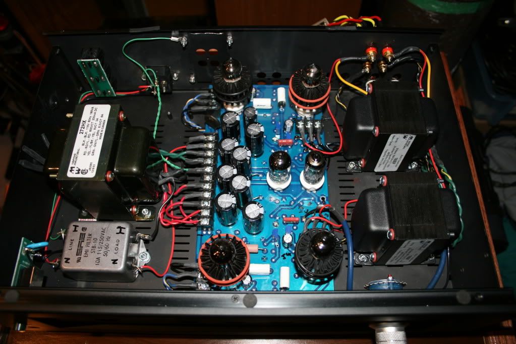
This one is a Rev B and is built into a recycled chassis, some hammond iron and parts I had lying around.

Fired right up, very quiet. Diddly hum on my ~100db sensitive sansui horns. This is a sweet amp and has a very enjoyable tube sound. This iteration has a nice midrange, not the last word in clarity but very nice. The bass is killer, taut, detailed and deep. Highs are extended and smooth. No rolled off extremes at either end.

Will be interesting to see how it compares to the other amp (better parts and Triode reissue iron). That one is 80% complete but I need a couple more bits and bobs for it before I can finish.

Tks to the designer and the board for a great amp and all the support.

BTW for anyone looking for an image to copy from, dont use this one. I flipped the tube around to the other side of the board and moved parts around to fit everything inside the chassis.

Cheers

Image

Image
keenlyside
 
Posts: 8
Joined: Mon Dec 06, 2010 2:55 pm
Location: Vancouver

Postby Quad » Wed Jan 05, 2011 5:33 am

Very neat and compact build. Looking excellent!
Is that a stepped attenuator you have?
Pls post a pic of the rear too.
Quad
KT88
 
Posts: 254
Joined: Mon Jan 14, 2008 6:54 am
Location: India

Re: First One Finished

Postby Ty_Bower » Wed Jan 05, 2011 7:01 am

keenlyside wrote:I flipped the tube around to the other side of the board and moved parts around to fit everything inside the chassis.


Sharp looking build. Nice work. That must be a Rev B board? I assume you put the sockets on the "correct" side, and moved the caps and other tall stuff to that side as well?

Neat looking chassis. That amp has an 80's NAD looking style to it.
"It's a different experience; the noise occlusion, crisp, clear sound, and defined powerful bass. Strong bass does not corrupt the higher frequencies, giving a very different overall feel of the sound, one that is, in my opinion, quite unique."
User avatar
Ty_Bower
KT88
 
Posts: 1494
Joined: Wed Mar 21, 2007 2:50 pm
Location: Newark, DE

Postby TomMcNally » Wed Jan 05, 2011 10:40 am

Very cool ... it's great when you can re-purpose and old box
and make something out of it. You can cut out an insert of
something and cover the unused holes, yet they will be there
if you ever want to add an input selector or something.

Nice job!

... tom
User avatar
TomMcNally
Darling du Jour
 
Posts: 2729
Joined: Sat Nov 19, 2005 2:19 pm
Location: Northfield, NJ

Tks

Postby keenlyside » Wed Jan 05, 2011 11:32 am

Thanks all:

Is that a stepped attenuator you have?
Pls post a pic of the rear too.


Yes it is one of the cheap ones from Fleabay. Amazing that you can get an attenuator for less than a good pot these days. This one is a series style with SMT resistors. The next build has a larger ladder style with through hole resistors. Will post a pic of the rear tonight.

That amp has an 80's NAD looking style to it.


Too true, an AMC tube preamp I got some ways back that was a POS. Nice chassis though...

That must be a Rev B board? I assume you put the sockets on the "correct" side, and moved the caps and other tall stuff to that side as well?


Yep, it is a Rev B and that is exactly what I did. I also had to offset some of the caps to keep them away from the 12AU7 tube. The biggest pain was figuring out how to mount the trim pots on a reverse layout, didn't want to get it wrong but my pea brain is a bit dislexic at the best of times so I really had to scratch my chin to figure this one out.

Cheers
keenlyside
 
Posts: 8
Joined: Mon Dec 06, 2010 2:55 pm
Location: Vancouver

Postby EWBrown » Wed Jan 05, 2011 3:27 pm

Nice unit! (love)

The pots mounted on the "wrong" side of the PC board will still work, just the change of resistance vs rotation will be reversed.

I haev assembled both a rev B and a rev D board this way, for a couple of "custom" builds in the past. The only critical thing is to make sure that the tube sockets are correctly mounted on the "top" side of the boards, the rest of teh parts can go on either side, or mixed on both sides , as needed.

FWIW, the 12AU7 doesn't get hot enough to adversely affect the electrolytic caps, I just mounted them in their original positions with no problems.

/ed B
Real Radios Glow in the Dark
User avatar
EWBrown
Insulator & Iron Magnate
 
Posts: 6389
Joined: Wed Mar 19, 2003 6:03 am
Location: Now located in Clay County, NC !

Postby Geek » Wed Jan 05, 2011 7:10 pm

Awesome job! Well done! (wine)

Cheers!
-= Gregg =-
Fine wine comes in glass bottles, not plastic sacks. Therefore the finer electrons are also found in glass bottles.
User avatar
Geek
KT88
 
Posts: 3585
Joined: Sun Oct 21, 2007 3:01 am
Location: Chilliwack, British Columbia

Postby Writer Frog » Wed Jan 05, 2011 8:56 pm

I love the workmanship and the end result. A thing of beauty!
/Matt
User avatar
Writer Frog
 
Posts: 95
Joined: Mon Mar 06, 2006 9:17 am

Rear Pic

Postby keenlyside » Thu Jan 06, 2011 12:10 am

Pls post a pic of the rear too.


Here you go. I added a fused IEC as the original uint had a captive AC cord which I find to be a pain in the butt. Popped some holes in for the Binding Posts and (as Tom mentioned) used existing holes for the RCA's.

Image

The pots mounted on the "wrong" side of the PC board will still work, just the change of resistance vs rotation will be reversed.


Good to know, I had horrible visions of firing it up with max bias current or some similar bad bad bad.


Question for the group. Anyone know the max operating tem for a Hammond Power Transformer (272HX)? It runs around 66 deg C in this chassis which is a schooch hotter than I am used to but seems ok.....
keenlyside
 
Posts: 8
Joined: Mon Dec 06, 2010 2:55 pm
Location: Vancouver

Postby EWBrown » Thu Jan 06, 2011 9:36 am

With the four bias pots, I pre-set them so that the resistance from the 6BQ5 sockets' pin 3 (cathode) measure 400 ohms to ground. With that setting, the bias and cathode/plate current will be fairly close to 35 mA each.

Same goes for the two NFB pots, just preset them for 27K (16 ohms) or 19.2K (8 ohms). They shouldn't need any further tweeking after that

/ed B
Real Radios Glow in the Dark
User avatar
EWBrown
Insulator & Iron Magnate
 
Posts: 6389
Joined: Wed Mar 19, 2003 6:03 am
Location: Now located in Clay County, NC !

Postby Marshman » Fri Jan 07, 2011 11:13 am

Beautiful build!!

Where does one get those cool tube coolers? Manufacturer??

Thanks!

mm
Marshman
 
Posts: 34
Joined: Mon Jul 18, 2005 12:43 pm

Postby keenlyside » Fri Jan 07, 2011 11:52 am

Where does one get those cool tube coolers?


Manufacturer is Pearl Hi Fi out of Calgary

http://www.pearl-hifi.com/

I get them from Parts Connexion

http://www.partsconnexion.com/tube_cool_pearl.html

They work well, channeling heat up and out of the chassis. I was initially worried that they would radiate more of the heat outwards thereby heating up the power transformer more, this turned out not to be the case and I am glad I used them
keenlyside
 
Posts: 8
Joined: Mon Dec 06, 2010 2:55 pm
Location: Vancouver

Postby Marshman » Fri Jan 07, 2011 12:06 pm

Fantastic!!

Thanks so very much!!

mm
Marshman
 
Posts: 34
Joined: Mon Jul 18, 2005 12:43 pm


Return to stereo 35

Who is online

Users browsing this forum: No registered users and 8 guests