Page 1 of 1
ST-35 Cap Rating Question

Posted:
Mon Dec 06, 2010 4:47 pmby keenlyside
Building a ST-35 with the Triode reissue Transformers, the Rev C Board and Parts/Chassis. Very excited!
For C1, C2, C3, C4 the manual lists a 0.1uf 400v rated capacitor (an orange drop Vishay) but included a 630V part. I have some 400v rated film/foil capacitors I would like to use but is the 400v rating ok?
Apologize if the answer is somewhere in the forum, I did a search and could not find...
Cheers
Posted:
Mon Dec 06, 2010 5:55 pmby TomMcNally
Welcome to the forum!
400 volt caps are fine.
Let us know if you have any questions, and post
some pix when you're finished.
... tom
Thank You
Posted:
Tue Dec 07, 2010 1:15 amby keenlyside
Thanks Tom, thats great.
I will be back with more questions and pics. I am actually building a pair here, I had a board (rev B) and a set of Hammond Transformers I was going to build into an old chassis I have from a dead tube preamp. I gave up waiting to get the time for fiddling around with the chassis so I ordered a new chassis from Triode only to realize it does not fit the rev B board......
I think you can figure out the rest of this story as I now have all the parts for two ST-35 (a rev B and a rev C). Will be able to compare them when they are done and see how each sounds.
Cheers again and tks for the help.
John
Re: Thank You
Posted:
Tue Dec 07, 2010 5:52 amby Ty_Bower
keenlyside wrote:I ordered a new chassis from Triode only to realize it does not fit the rev B board...
I built my ST35 around the B board. I think I still have the Visio template I used for drilling the chassis. You're welcome to it if you'd like, although I didn't use the Dynaco transformers so some modification was required.
Posted:
Tue Dec 07, 2010 7:20 amby Geek
Now THAT is a decent aluminum plate top!
Definately not that "Reynolds wrap" Hammond/BUD flogs ;^)
Cheers!
Posted:
Fri Dec 10, 2010 1:19 amby keenlyside
Love the studs! I should have kept some of those from my renovations

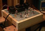
I am putting the gear into a (well ventilated) enclosed chassis so I just popped some bolt holes in the bottom where needed.
Should have some pics in a week or so.
Cheers, and tks.
Ohm it out
Posted:
Sun Dec 19, 2010 11:11 amby keenlyside
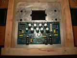
I have finished populating the Rev C board and have only one reading that doesn't match the manual. Gnd to Pin 1 on J6 (and also on J7) is supposed to be >10M but is 0.5M on my board.
Looking at the schematic and the stuffing guide, I think 0.5M makes sense as C14 / C15 would have kept this cct above 10M but are shown in the BOM as jumpers which when installed would have the DMM reading R2 plus R4 / R1 plus R3.
Hoping for a second opinion before I move forward.
Tks, lots of fun thus far!


