Posted:
Fri Dec 17, 2010 1:46 pmby cedricb
After further listening, I'm getting a constant buzz on both speakers. I didn't have this issue with the 230V tap with the higher B+. I believed this is due to the lower filament voltages.
So I've ordered a 20V/ 20W zener diode to use on the CT; I should get a B+ of around 297VAC.
Is there anything I need to consider when plugging this zener between the CT and the PCB J1-5 connector?

Posted:
Mon Dec 20, 2010 7:28 amby dcgillespie
Cedric -- The buzz you're hearing likely has nothing to do with the transformer voltage taps you are using, unless in changing the taps it caused AC power wires to somehow come in close proximity to the input wiring, which I doubt. An AC buzz is usually due to ground loops in the wiring, or heaters that are not properly referenced to ground. I would check these things first, as most folks report that these amps are dead quiet when built as instructed.
As to your Zener diode option, if you get a 20 volt device, it will allow the best of both worlds for your operating conditions. If you install it, you could then restore the AC power to the original AC taps on your transformer, which would then restore the proper 6.3 vac to your heaters. It would also push the available B+ back up to 400 vdc, but with a 20 volt Zener installed, it would drop this back to an operating B+ of around 380 vdc. Accounting for about a 10 volt drop in the OPT primary winding, and about 14 volts across the bias resistor, this means there will be about 356 vdc develop across the tubes. If you then set the bias for 35 ma. per tube cathode current draw, the plate current component of this figure is about 31 ma. With 356 volts effectively dropped across each tube, this equals 11 watts of plate dissipation per tube, which is within safe operating parameters.
Doing this will also restore your cathode voltage readings (pin#3) to more traditional values. Realize that just as the control grid of any tube (pin#2 in this case) always controls the current flow through the tube, so does the screen grid as well (pin#9 in this case) in pentode tubes. Therefore, since these are UL amplifiers, reducing the operating B+ from 400 volts down to 380 volts by the Zener also reduces the screen grid voltage as well. This then reduces current draw, which then allows more normal cathode bias voltages to be developed when achieving the target current draw.
Good luck with your amp!
Dave
Posted:
Tue Dec 21, 2010 10:15 amby cedricb
@dcgillespie: thanks for the details response! ...for the buzz I didn't changed anything a part of using a different tap on the transformer and re-adjsuting the bias.
I'm still waiting on the zener; the supplier has issue with the delivery due to the bad weather in Europe...
I'll have a look at my wiring after installing the zener on the CT. On the Weber site for their V-Dump device; they are recommending to use a ceramic cap across the zener to reduce the noise from the reverse voltage. Do I really need 1KV for the cap? 0.1uf 1KV
Posted:
Tue Dec 21, 2010 3:42 pmby dcgillespie
It's always a good idea to install a cap across a Zener, but I would want to know where they are recommending the Zener to be installed in the circuit before commenting on a voltage rating for a cap across it. In any event, it would be hard to imagine a cap requiring more than a 600 volt rating for such a low voltage Zener.
Dave
Posted:
Wed Dec 22, 2010 12:41 amby cedricb
dcgillespie wrote:It's always a good idea to install a cap across a Zener, but I would want to know where they are recommending the Zener to be installed in the circuit before commenting on a voltage rating for a cap across it. In any event, it would be hard to imagine a cap requiring more than a 600 volt rating for such a low voltage Zener.
Dave
On their descriptive page (
https://taweber.powweb.com/store/vdump.htm), the CT tap is connected to the chassis ground therefore the zener is added between the CT and the chassis.
For the DiyTube board, I'll install the zener between the center tap and the PCB ground connection.
Posted:
Tue Jan 11, 2011 7:54 amby cedricb
I've finally received my zener diode!
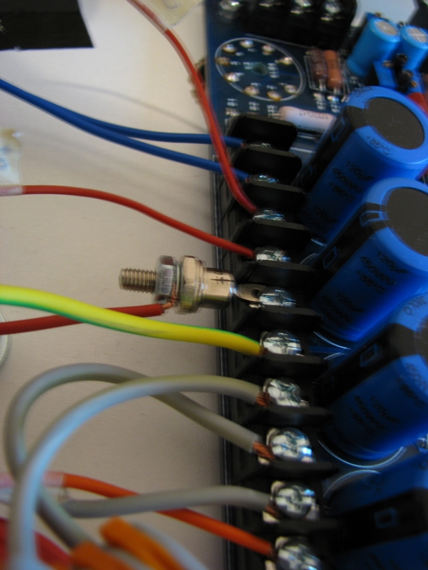
I've connected the center tap on the cathode and the PCB ground to the anode. I'm getting 8.9VAC across the diode (BZY93C20).
I don't seem to see any difference across 1 and 5 (J1) vs 1 and the cathode...
....am I missing something?
Posted:
Tue Jan 11, 2011 2:45 pmby cedricb
...by changing the polarity on the zener, I'm getting the correct result...

...so now I've got the anode on the CT and the cathode on the ground. I'm getting the correct voltages with the 230V tap!
...the zener is extremely hot, I can't touch it after power down! I need to add metal bracket and get isolated on the chassis.
I just found out the issue with my constant "hissssss"; if I'm using my sound card as input!!! Dead quiet with my portable CD player. Any idea why? ground loop?

Posted:
Tue Jan 11, 2011 3:51 pmby dcgillespie
Cedric -- I was going to suggest that for this application, you have the Zener installed backwards, but you already found that out! It needs to be heat sinked, or you will damage it quickly.
It seems to me that the hiss is coming from the sound card itself?
Dave
Posted:
Fri Jul 29, 2011 1:17 pmby cedricb
...I've still haven't finish the final chassis... after moving back to the UK, I'm back on the DIY wagon!
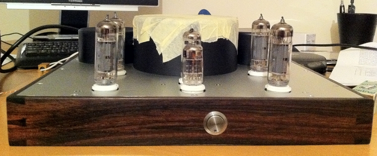
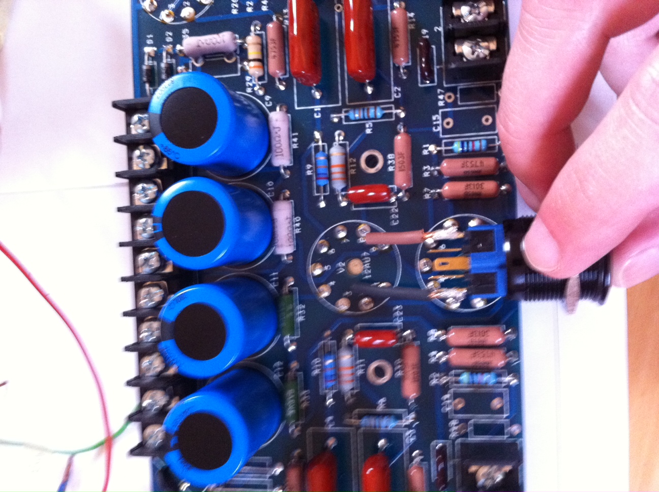
Anyway due to the space issue with my designed chassis, the power switch (230V) will sat nearly on top of the 12AX7. I've got a clearance with the PCB of 10mm...
Is that an issue in term of potential hummmm?
Posted:
Tue Aug 02, 2011 2:00 amby cedricb

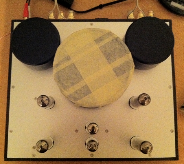
The top panel is 320x270mm and the outer chassis (wood) will be 330x280mm, so I don't really want to increase the chassis size; it's already huge...
I've got some space behind the main transformer on the panel but I would like to have the power switch on the front section like a standard hifi device.
I could move a little bit the PCB backward but the rear EL84s will be too close to the main transformer; it's a potted toroid so the issue will be heat. At the moment the space between the main transformer and the rear EL84s is around 25/30mm. In the first post you can see the spaces.
By positioning the switch in alignment with V1, I'm keeping a nice symmetry!

Posted:
Tue Aug 02, 2011 5:47 amby Shannon Parks
I think you'll be A-OK and hum-free with that switch.

Shannon
Posted:
Sun Dec 18, 2011 12:16 pmby cedricb
Posted:
Tue Dec 20, 2011 2:08 pmby cedricb
I've changed the zener and same story I can't get a drop of voltage!?!

I've removed the zener from the aluminium bar and same issue... don't know where is my mistake.
Posted:
Fri Dec 23, 2011 2:57 pmby cedricb
I know it's Christmas time, but do you have any suggestion how to diagnostic this issue?