European build

for the DIY ST35, the Dynakit and every other PP EL84

Postby Shannon Parks » Fri Dec 23, 2011 3:57 pm

cedricb wrote:I know it's Christmas time, but do you have any suggestion how to diagnostic this issue? (???)


Let me re-read this whole thread, Cedric, and see what I can sort out.

Shannon
User avatar
Shannon Parks
Site Admin
 
Posts: 3764
Joined: Tue Mar 18, 2003 5:40 pm
Location: Poulsbo, Washington

Postby Shannon Parks » Sat Dec 24, 2011 7:15 am

Cedric,

Hope you can get it going before Christmas.

1) I realize you just replaced the zener, but I would scrap it. Your voltages are A-OK on all your tubes without it. Eliminating it removes an extra wasted heat source in your amp and a potential failure mechanism (i.e. diodes can die quickly and easily).

2) Back to your filaments, all the voltages you listed are great. You can certainly remove and jumper R36 and R37 if you haven't already.

3) What do you mean a drop of voltage? Do you mean no B+, or no voltage drop across the zener? Anyhow, remove the zener, and check your diodes at D1 and D2 with the diode checker on your DMM. See if one is blown open.

Shannon
User avatar
Shannon Parks
Site Admin
 
Posts: 3764
Joined: Tue Mar 18, 2003 5:40 pm
Location: Poulsbo, Washington

Postby Shannon Parks » Sat Dec 24, 2011 7:21 am

Oh - check the fuse, too.

Shannon
User avatar
Shannon Parks
Site Admin
 
Posts: 3764
Joined: Tue Mar 18, 2003 5:40 pm
Location: Poulsbo, Washington

Postby cedricb » Wed Dec 28, 2011 12:14 pm

What I meant by voltage drop; I can't lower the secondary, I'm getting around 326vac and 384V on pin 7 of the power tubes, instead of 360V.

It looks like I'm getting the correct voltage accros the Zener but it doesn't reduced the secondary...

I could get it working with my temporary MDF plate but not correctly with the new case/plate. I've insolated the aluminium bar with an insolated pad.
cedricb
 
Posts: 89
Joined: Mon Jan 28, 2008 4:49 am

Postby Shannon Parks » Thu Dec 29, 2011 5:48 am

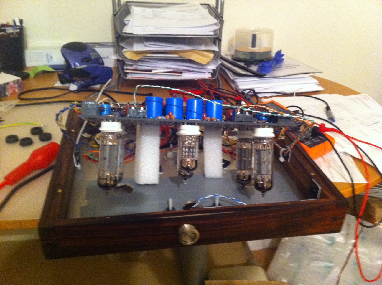
cedricb wrote:What I meant by voltage drop; I can't lower the secondary, I'm getting around 326vac and 384V on pin 7 of the power tubes, instead of 360V.

It looks like I'm getting the correct voltage accros the Zener but it doesn't reduced the secondary...

I could get it working with my temporary MDF plate but not correctly with the new case/plate. I've insolated the aluminium bar with an insolated pad.


384V for the B+ is fine.

As far as "not working", do you mean no sound? No bias at the cathode resistors? Have you retaken all your voltages?

If it was working on the MDF, then transferred, it must presumably be a wiring error.

Shannon
User avatar
Shannon Parks
Site Admin
 
Posts: 3764
Joined: Tue Mar 18, 2003 5:40 pm
Location: Poulsbo, Washington

Postby cedricb » Thu Dec 29, 2011 3:31 pm

what I meant; is my zener trick is not working as expected.

I'm getting 310VAC on block 1 or 2. With the zener I'm getting 325V, it should subtract not added up! Anyway for the time being, I've wired the CT directly to block 6/5.

In my new house the main is at ~237VAC. Here are the different voltages with the primary 240V tap:

V1 - 1 = 99.5V
V1 - 3 = 930mV
V1 - 6 = 103V
v1 - 8 = 918mV
v1 - 9 = 3.065VAC
v1 - 4 = 3.045VAC
v1 - 5 = 3.055VAC

v2 - 1 = 239V
v2 - 2 = 99V
v2 - 3 = 109V
v2 - 6 = 240V
v2 - 7 = 103V
v2 - 8 = 109V
v2 - 4 = 3.050VAC
v2 - 5 = 3.060VAC
v2 - 9 = 3.060VAC

v3 - 3 = 16.5V
v3 - 7 = 382V
v3 - 9 = 384V
v3 - 4 = 3.060VAC
v3 - 5 = 3.020VAC

v4 - 3 = 8.90V
v4 - 7 = 381V
v4 - 9 = 382.5V
v4 - 4 = 3.022VAC
v4 - 5 = 3.000VAC

v5 - 3 = 7.20V
v5 - 7 = 382V
v5 - 9 = 386V
v5 - 4 = 3.090VAC
v5 - 5 = 3.060VAC

v6 - 3 = 13.50V
v6 - 7 = 381V
v6 - 9 = 384V
v6 - 4 = 3.105VAC
v6 - 5 = 3.084VAC

I can't bias correctly V5 and V4, I've kept the tubes in storage for the last 6 months. A bit weird that I can't bias them correctly as before...

with V3, I can't bias under 365mV; I've tried 2 different tubes...

same thing with V4, I can't bias upper 240mV, I've tried as well with the tubes which strongly bias on V3.

the only one which bias correctly at 350mV is V6.

something wrong here... =:o
cedricb
 
Posts: 89
Joined: Mon Jan 28, 2008 4:49 am

Postby cedricb » Wed Feb 15, 2012 1:32 pm

...it looks like my multimeter was broken, cheap Chinese one -> Vichy VC99 :/
I've got an old analogue multimeter and I've set for the time being roughly the bias voltages between 320 and 370mV.

With the speaker connected, I'm getting after 30s a loud motor-boating sound on both speakers (with the music in the background).
cedricb
 
Posts: 89
Joined: Mon Jan 28, 2008 4:49 am

Postby TomMcNally » Wed Feb 15, 2012 8:50 pm

That sounds like the typical feedback problem when the transformer
primary phase is backward. Reverse the leads end to end of both
the plates and screens.

ie: swap the connections from:

j2 1 to j3 1
j3 2 to j3 2
j4 1 to j5 1
j4 2 to j5 2

That should fix it.
User avatar
TomMcNally
Darling du Jour
 
Posts: 2729
Joined: Sat Nov 19, 2005 2:19 pm
Location: Northfield, NJ

Postby cedricb » Fri Feb 17, 2012 2:32 pm

I've swapped J2 to J3 (and vice versa) and J4 to J5 (and vice versa). I'm getting an enormous distortion/hiss... 10 times louder than before!

I've got the plates on 1 and the screens on 2. Before the swap:
- plate/screen 1 were wired to J3 and J4
- plate/screen 2 were wired to J2 and J5
cedricb
 
Posts: 89
Joined: Mon Jan 28, 2008 4:49 am

Postby cedricb » Fri Feb 17, 2012 3:27 pm

I've swapped again as before. It looks like I'm getting correct sound at the beginning and when the tubes are fully warmed up; the motor-boating starts...

With the swap around the distortion/hiss was really loud and I couldn't hear the music in the background.
cedricb
 
Posts: 89
Joined: Mon Jan 28, 2008 4:49 am

Postby cedricb » Sun May 27, 2012 8:25 am

Hi Guys,

I've got some free time to diagnostic my non-working amp. I can't find anything wrong with my wiring.

Is there somebody from the UK which could help me out? ;)
cedricb
 
Posts: 89
Joined: Mon Jan 28, 2008 4:49 am

Postby cedricb » Wed Oct 17, 2012 11:57 am

I've started again my powered-boat tonight!
I've just check the ground (connector J1: 5 or 6) and it looks like is connected to my aluminium top plate and the bolts from the 3 toroids. Is that an issue? ...don't know why it's interconnected?!? (???)
For the time been I haven't connected the earth ground from the power connector.

...I just have enough with this build... :'(
cedricb
 
Posts: 89
Joined: Mon Jan 28, 2008 4:49 am

Postby cedricb » Wed Oct 17, 2012 1:55 pm

>:o >:o ...with the board floating from the chassis; the sound is perfect!! ...the amp has been on the shelf for several months!! (sick)
cedricb
 
Posts: 89
Joined: Mon Jan 28, 2008 4:49 am

Postby cedricb » Fri Oct 19, 2012 1:07 pm

I've tapped the entire top plate area (with an electrical tape) where the PCB sat. It look like the chassis is not connected to the signal ground, which is better...

...guess what; the motor boated sound is back! I don't get it! There are some plastic spacers (~0.6cm) between the top plate and the PCB.

The only things which are in contact with the chassis; the transformer bolts and the 6 screws to hold the PCB.

Any help will be greatly appreciated. :$
cedricb
 
Posts: 89
Joined: Mon Jan 28, 2008 4:49 am

Postby cedricb » Tue Oct 23, 2012 2:57 pm

I've tried Teflon screws for the PCB and same issue.

It works "perfectly" like this...

Image

Am I getting an electromagnetic thing from the top plate?
cedricb
 
Posts: 89
Joined: Mon Jan 28, 2008 4:49 am

PreviousNext

Return to stereo 35

Who is online

Users browsing this forum: No registered users and 5 guests