by EWBrown » Wed Dec 01, 2010 10:47 am
I found, a couple years ago, that the Trafomatic ST35 power transformers do run higher B+ voltages than normal for EL84s. In my case, I had approximately 400VDC at the OPT centertaps, which is 35VDC higher than normal ST35 operation (365VDC) The Russian made EL84s / 6P14Ps are inexpensive and easily available enough so that shortened tube life isn't really as much of a problem as it would be with choice Telefunkens, Mullards, NOS USA 6BQ5s, etc.
There are two simple solutions, first is to use a 10 to 12 VAC 2A (or greater) transformer to "buck" the incoming (230-340 Volt) AC power line voltage by approximately 5%, and the other is to bias the tubes slightly lower than 35 mA, try 32 to 33 mA (320 to 33o mV) , this should lower the plate dissipation sufficeintly, and not affect the sound quality.
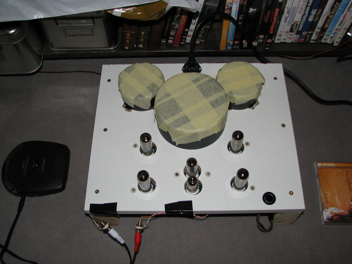
As far as the "boomy" bass, are you using a preamplifier with tone and loudness controls? (In the photo, it looks like you have direct conenction from the CD player to the ST35 amp)
If you are, try setting them to the "neutral" center position, and turning off the "loudness" contour switrch if there is one. If you are using the "headphone" output of teh CD player, rather than the "line" output, it may have bass boost and somewhat "flabby" sound, as this is intended to work into a 32 to 300 ohm impedance. The line output should be a lot "cleaner" sounding.
In my systems, I use only volume controls, and "balance" in a couple of builds. No tone controls, loudness, equalizers, etc to modify or mangle the sound.
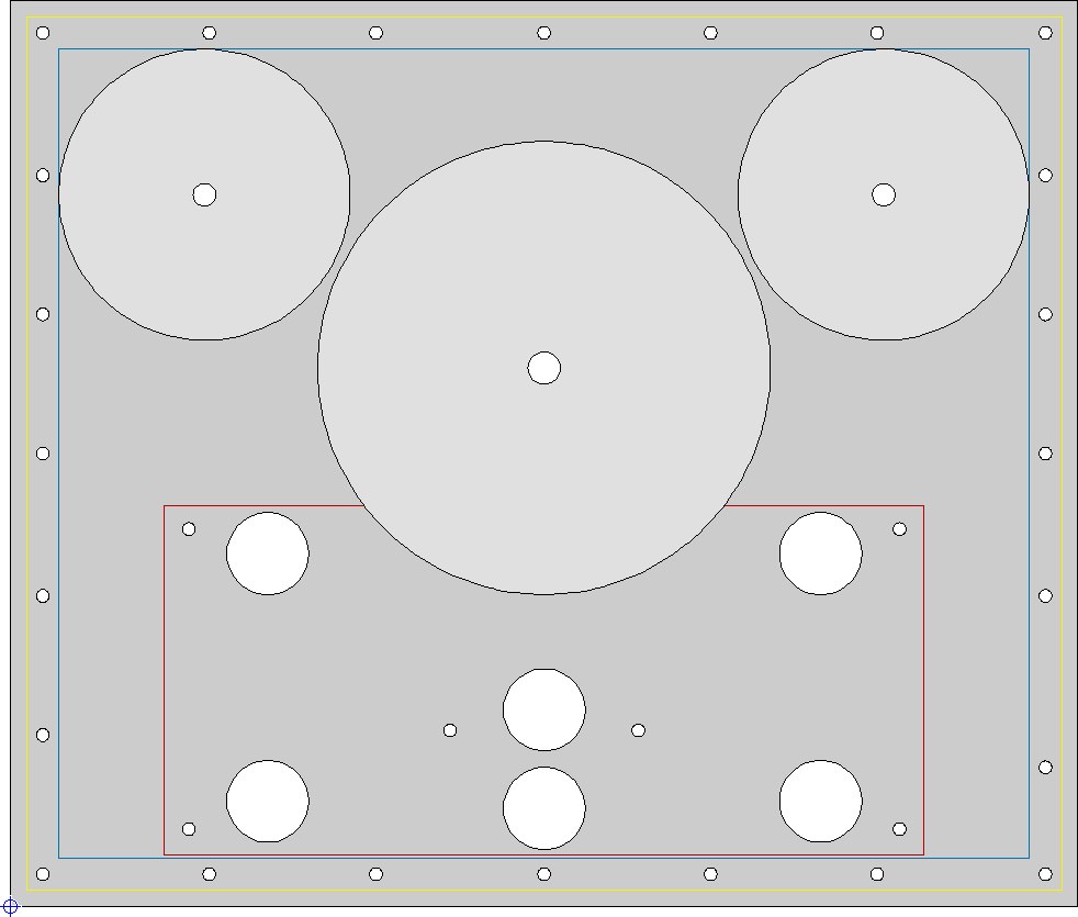
The chassis holes around the tube sockets are more than sufficient for vertical air circulation around the tubes, no need for any more drilled holes.
/ed B
Real Radios Glow in the Dark