Hi again everybody!
With a little help and a suggestion or two from a few of the great members here, I have started my first tube amp build.
I am building the ST-35 kit from Triode Electronics. The kit had everything except for a few bits of hardware and crimp terminals. With everything now in hand (I think), I have started soldereing things up.
I have set up a Personal Album and will post pictures of my progress over there.
Hopefully, in a few days, I will have sweet tunes flowing...
Cheers!
Scott
My first tube amp build.
25 posts
• Page 1 of 2 • 1, 2
More pictures have been posted
I have added a few more pictures to my Photo Album that show the PC board in it's completed state.
Now, onto the chassis....
Now, onto the chassis....
-

SVinzant - Posts: 53
- Joined: Mon Sep 27, 2010 12:53 pm
- Location: Quad Cities, IL
Looking good Scott!
I was wondering why you took all of the screws out of
the barrier strips? That must have been a tedious job.
I was wondering why you took all of the screws out of
the barrier strips? That must have been a tedious job.
-

TomMcNally - Darling du Jour
- Posts: 2729
- Joined: Sat Nov 19, 2005 2:19 pm
- Location: Northfield, NJ
Looks good so far... what kind of speakers are they going to play?
"It's a different experience; the noise occlusion, crisp, clear sound, and defined powerful bass. Strong bass does not corrupt the higher frequencies, giving a very different overall feel of the sound, one that is, in my opinion, quite unique."
-
Ty_Bower - KT88
- Posts: 1494
- Joined: Wed Mar 21, 2007 2:50 pm
- Location: Newark, DE
TomMcNally wrote:Looking good Scott!
I was wondering why you took all of the screws out of
the barrier strips? That must have been a tedious job.
Tom, thanks for the thumbs up!
RE: The screws, I thought I have a better soldereing experiance by not having to heat the pin / hole AND the screw. I reasoned that it might act like a small heat sink and pull the heat away from the "objective" of making a strong connection. Afterall, there will be some "stress" on this point when tightning the screw down.
As far as tedious, I think I have OCD, so it was "fun"!

Putting them all back in will be fun too.

-

SVinzant - Posts: 53
- Joined: Mon Sep 27, 2010 12:53 pm
- Location: Quad Cities, IL
Ty_Bower wrote:Looks good so far... what kind of speakers are they going to play?
Thanks, Ty.
As far as speakers, I don't know yet. For testing, I have some old "garage" speakers that won't hurt my feeling if they get blown up!
I don't really have too much in the way of test equipment (read that as an old DMM) to "see" what is going on.
I do have a pair of Paradigm "mini monitors" "7" may have been the model number. I may try them and see how the sound.
They were doing duty as surround speakers at our old house, but were not able to be used in our new house due to a different room layout.
I have also had some interest in that new Frugel-Horn Mk3 plan that Planet10 posted over at diyAudio.com
My garage is heated, so building that might be a great winter project.
I also need to figure out something for a phono preamp for my old TT.
Cheers...
Scott
-

SVinzant - Posts: 53
- Joined: Mon Sep 27, 2010 12:53 pm
- Location: Quad Cities, IL
While I still have the soldering iron hot....
I thought I saw somewhere that I may need to short the inputs while testing / or setting the bias.
Should I have the center pins of the left and right RCA input jacks tied together?
Or, should I have the center pin of each RCA jack grounded?
And I am assuming that I should have the tubes in while I set the bias, is that correct?
I'm getting close to completion and am getting excited.
Thanks again for the support!
Scott
Should I have the center pins of the left and right RCA input jacks tied together?
Or, should I have the center pin of each RCA jack grounded?
And I am assuming that I should have the tubes in while I set the bias, is that correct?
I'm getting close to completion and am getting excited.

Thanks again for the support!
Scott
-

SVinzant - Posts: 53
- Joined: Mon Sep 27, 2010 12:53 pm
- Location: Quad Cities, IL
Re: While I still have the soldering iron hot....
SVinzant wrote:I thought I saw somewhere that I may need to short the inputs while testing / or setting the bias.
It's handy to have a set of "shorting plugs." It's just an old audio patch cable with a RCA plug on the end. Cut the end off, leaving a couple inches of wire. Strip back the insulation, exposing the wires. Twisting the signal and ground together, and solder and heatshrink if you like. Do the same to the other end of the cable, and now you've got a pair of shorting plugs.
If you don't want to sacrifice an old patch cable, just slip a one inch jumper wire between terminals 1 and 2 on J6. Do the same thing for J7. You're not trying to short the left channel to the right - you're shorting each channel to ground.
Another tip to keep in mind - always have a load on the output while the amp is powered on. You can use an old pair of speakers for the maiden voyage, but don't use your good speakers in case something bad happens to them. You can also use one of those 8 ohm, 20 watt cemented resistors You can find them at Radio Shack for $2.50 a piece. You would need one for each channel. In any case, never leave the outputs disconnected while the amp is on. Transformer damage can result.
Finally, it is recommended practice to let the amp cool off after you turn it off. Don't turn the amp back on while it is still hot.
Good luck, have fun, and be safe!
"It's a different experience; the noise occlusion, crisp, clear sound, and defined powerful bass. Strong bass does not corrupt the higher frequencies, giving a very different overall feel of the sound, one that is, in my opinion, quite unique."
-

Ty_Bower - KT88
- Posts: 1494
- Joined: Wed Mar 21, 2007 2:50 pm
- Location: Newark, DE
The easiest shorting plugs I've ever used is a cheap stereo RCA cable with one end "mated" (i.e. jammed together). Works great and can be reversed. 
--Shannon

--Shannon
-

Shannon Parks - Site Admin
- Posts: 3764
- Joined: Tue Mar 18, 2003 5:40 pm
- Location: Poulsbo, Washington
It's making music to my ears!
Hi again everybody.
My amp is complete, and playing music from my iPOD at the moment (Dire Straits) and sounds WONDERFUL.
Dead quite.
I have posted more pics in the photo album.
There is one small hitch, the four large filter caps (C9 thru C12) are a bit to tall for the bottom cover to go on the SS chassis from Triode.
I pulled the stand-offs out and replaced them with 6-32 .75" long screws thinking I could get a bit of clearance, but, this still is not enough.
I haven't screwed the bottom cover on as of yet, but when I test fit it, there is a noticeable gap at the front edge of the chassis where the bottom cover meets the rolled over edge of the top chassis
Has anybody else had this problem?
I may have to ponder this for a day or two...
I think I am now needing a linestage with a phono pre-amp so I can control the volume.
I may have to rig up a pot in the meantime so I can pull my turntable (1980's Techniques SL-B2 + Audio-Technica cartridge) out of storage so I can spin some vinyl! I know it's nothing fancy, but it works for me!
Cheers!
Scott
My amp is complete, and playing music from my iPOD at the moment (Dire Straits) and sounds WONDERFUL.
Dead quite.
I have posted more pics in the photo album.
There is one small hitch, the four large filter caps (C9 thru C12) are a bit to tall for the bottom cover to go on the SS chassis from Triode.
I pulled the stand-offs out and replaced them with 6-32 .75" long screws thinking I could get a bit of clearance, but, this still is not enough.
I haven't screwed the bottom cover on as of yet, but when I test fit it, there is a noticeable gap at the front edge of the chassis where the bottom cover meets the rolled over edge of the top chassis

Has anybody else had this problem?
I may have to ponder this for a day or two...
I think I am now needing a linestage with a phono pre-amp so I can control the volume.
I may have to rig up a pot in the meantime so I can pull my turntable (1980's Techniques SL-B2 + Audio-Technica cartridge) out of storage so I can spin some vinyl! I know it's nothing fancy, but it works for me!
Cheers!
Scott
-

SVinzant - Posts: 53
- Joined: Mon Sep 27, 2010 12:53 pm
- Location: Quad Cities, IL
Re: It's making music to my ears!
SVinzant wrote:There is one small hitch, the four large filter caps (C9 thru C12) are a bit to tall for the bottom cover to go on the SS chassis from Triode.
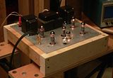
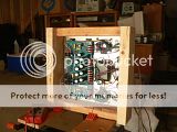
Hmm. That's a bit awkward, isn't it? I built mine on a clumsy looking box made of 2x4 framing lumber. It has no bottom at all. Even still, you paid Triode good money for a chassis with a bottom. Maybe give them a call and see what they suggest?
I think I am now needing a linestage with a phono pre-amp so I can control the volume.
I like my Adcom GTP-500 II quite a bit. You'll sometimes see them go on eBay for $100 or so. It has a phono preamp and is remote controlled. I wouldn't hesitate to recommend it.
"It's a different experience; the noise occlusion, crisp, clear sound, and defined powerful bass. Strong bass does not corrupt the higher frequencies, giving a very different overall feel of the sound, one that is, in my opinion, quite unique."
-

Ty_Bower - KT88
- Posts: 1494
- Joined: Wed Mar 21, 2007 2:50 pm
- Location: Newark, DE
Re: It's making music to my ears!
SVinzant wrote:There is one small hitch, the four large filter caps (C9 thru C12) are a bit to tall for the bottom cover to go on the SS chassis from Triode.
I pulled the stand-offs out and replaced them with 6-32 .75" long screws thinking I could get a bit of clearance, but, this still is not enough.
I haven't screwed the bottom cover on as of yet, but when I test fit it, there is a noticeable gap at the front edge of the chassis where the bottom cover meets the rolled over edge of the top chassis
Scott - first off, congrats!
Couple questions:
1) Is this the Rev C or Rev D?
2) Also, what Mouser part number did you use for the caps? Can you measure them in millimeters - diameter and height? Many thanks!
--Shannon
-

Shannon Parks - Site Admin
- Posts: 3764
- Joined: Tue Mar 18, 2003 5:40 pm
- Location: Poulsbo, Washington
Mouser has one that is below 30mm, a Pansonic that's 30mm wide X 25mm in length. The Cornell Dubilier in the parts list is 22MM wide X 30 in length. Looks like the Panasonic will be too wide.
At first I wanted to be a ET. Now I are one.
-
DeathRex - KT88
- Posts: 1014
- Joined: Wed Nov 18, 2009 8:13 pm
- Location: Cortez, CO
The rev C and D boards were origanlly designed to go in a Hammond 2" chassis. Then came along the Triode chassis, IMHO is the icing on the cake, but is only 1.75" tall! So if you use the big tube sockets and the caps on the parts list, it ain't gonna fit.
However you can replace the four caps with 25mm tall 100uf @ 450v and it will fit. 667-EET-HC2W101CA
However you can replace the four caps with 25mm tall 100uf @ 450v and it will fit. 667-EET-HC2W101CA
T. Smith
-

TerrySmith - KT88
- Posts: 973
- Joined: Sat Jan 31, 2004 12:51 pm
- Location: Maryville TN
The original specified standoffs are at least 1/4 too long for the Triode (or Soundtastic) SS chassis, I had to get the (Rev D) PC board, as close as safely possible, to the top of the chasis to fit (with 30mm X 22 mm caps) I used the "Soundtastic" chassis, which is no longer available.
I ended up using some 1/4 inch nylon spacers I found at the local hardware store. I had no issues with too-close spacing of the PC board's upper surface being too close to the underside of the chassis. Just make sure that everything on the solder side of the board is trimmed as "flush" as possible. Some form of insulating material, like Kapton or "Fish" paper could be used, if needed, to prevent any possible shorting to the chassis.
The tube sockets do jut above the top of the chassis, but I decided that was a small "sacrifice", in order to get everything to fit in / under the chassis.
re the gap, make sure that the bottom plate isn't bowed or warped, and also try rotating it front to back. Mine was slightly bowed outwards (downwards), and my "cure" was to use six stick-on rubber feet, one at each cormer of the bottom plate, and one at each mid-point of the front and back, which gives it a "hexapod" footprint. That closed up the gap very nicely.
/ed B
Real Radios Glow in the Dark
-

EWBrown - Insulator & Iron Magnate
- Posts: 6389
- Joined: Wed Mar 19, 2003 6:03 am
- Location: Now located in Clay County, NC !
25 posts
• Page 1 of 2 • 1, 2
Who is online
Users browsing this forum: No registered users and 6 guests
