Cedric -- Using your schematic, the "jumpers" (or the DPST switch) would be connected between pin #3 of V3 and pin #3 of V4, and the also between pin #3 of V5 and pin #3 of V6. That is why you would need a double pole switch to provide the necessary jumper function in both channels. Or, if you provide test point connectors at pin #3 of each output tube, you could also just use external jumpers (instead of the switch) between these connectors (one between the connectors for V3 & V4, and one between the connectors of V5 &V6) to accomplish the same thing. Therefore, none of these connections would be in parallel with any of the 10 ohm resistors, but rather, connected between the cathode end of these resistors in each channel.
The neat thing about having a global bias and individual bias controls, is that the individual controls allow for fine tuning between the four tubes, while the global control allows the overall adjustment window of the individual controls to be shifted up or down as the particular set of tubes being used requires.
To bias the amplifier, start with all the controls centered, and the jumpers (if used) removed, or alternately, the DPST switch set so that there is no connection made between pin #3 of each output tube. You can simply have your speakers connected, with no input applied. If you are providing test points to measure your current flow, you really need to have five of these installed to make for an easy effort of biasing the amplifier: One test point would be connected to pin #3 of each output tube as discussed above, while the fifth test point would connect to the Output terminal of the LM337 regulator. This fifth test point becomes the "common" terminal you use for your meter as you check the voltage at the test point connected to pin #3 of each output tube.
With power applied, you will likely find that with the controls centered, the current flow for all the tubes (as measured between the common test point and each output tube's individual test point) will be too low (i.e., less than 0.27 vdc). That is by design, as I developed the adjustment circuit to make it almost impossible to get into trouble (i.e. cause damaging amounts of current to flow) with the vast majority of output tube sets you might use.
Assuming the bias is too low (which it usually is), let the amplifier stabilize for a few minutes. Then, you can then use the global control to bring the current draw of all four tubes up close to the target voltage (.27 vdc), and then use the individual controls to adjust each tube to this exact value. Once you are satisfied the tubes have stabilized to the proper setting, then you can either install the external jumpers (or throw the switch) to connect pin #3 of the output tubes together in each channel. The jumpers can be removed or installed (or the switch thrown) while the amplifier is running without concern. Just remember that all of the five test points operate at some 14-15 volts above ground, so do not inadvertently short any of the test points to ground as you remove or install any meter leads or jumpers, as to do so would remove all bias from the tubes.
I'm happy to help as you work your way through your installation. I have no doubt that you will be well rewarded from your efforts in the end!
Dave
Improved SCA-35/ST-35 Performance
![]() by dcgillespie » Thu Oct 27, 2011 5:53 am
by dcgillespie » Thu Oct 27, 2011 5:53 am
- dcgillespie
- KT88
- Posts: 399
- Joined: Sun Mar 08, 2009 5:34 am
- Location: Ball Ground, GA
![]() by Shannon Parks » Thu Oct 27, 2011 6:41 am
by Shannon Parks » Thu Oct 27, 2011 6:41 am
Cedric,
Here is my first stab at modding the EFB for a Rev D. Lots of cuts and jumpers, but doable. It wouldn't be difficult to modify the current layout for the EFB.
http://www.diytube.com/st35/revefb.txt
http://www.diytube.com/st35/revefb.jpg
There may be errors. Also, it hasn't been tested. Note that I have shifted the current sense resistors between Vin and ground.
Shannon
-

Shannon Parks - Site Admin
- Posts: 3764
- Joined: Tue Mar 18, 2003 5:40 pm
- Location: Poulsbo, Washington
![]() by cedricb » Thu Oct 27, 2011 10:08 am
by cedricb » Thu Oct 27, 2011 10:08 am
dcgillespie wrote:Cedric -- Using your schematic, the "jumpers" (or the DPST switch) would be connected between pin #3 of V3 and pin #3 of V4, and the also between pin #3 of V5 and pin #3 of V6. That is why you would need a double pole switch to provide the necessary jumper function in both channels. Or, if you provide test point connectors at pin #3 of each output tube, you could also just use external jumpers (instead of the switch) between these connectors (one between the connectors for V3 & V4, and one between the connectors of V5 &V6) to accomplish the same thing. Therefore, none of these connections would be in parallel with any of the 10 ohm resistors, but rather, connected between the cathode end of these resistors in each channel.
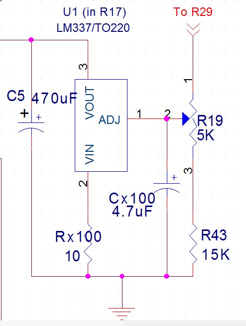
I've updated my schematic on my original post. The jumpers are labelled JP1 and JP2. The thing I don't understand if I'm shorting the cathodes together per channel then the ouput from the regulator wouldn't be used... Is there a drawing mistake on my schematic?
dcgillespie wrote:
The neat thing about having a global bias and individual bias controls, is that the individual controls allow for fine tuning between the four tubes, while the global control allows the overall adjustment window of the individual controls to be shifted up or down as the particular set of tubes being used requires.
To bias the amplifier, start with all the controls centered, and the jumpers (if used) removed, or alternately, the DPST switch set so that there is no connection made between pin #3 of each output tube. You can simply have your speakers connected, with no input applied. If you are providing test points to measure your current flow, you really need to have five of these installed to make for an easy effort of biasing the amplifier: One test point would be connected to pin #3 of each output tube as discussed above, while the fifth test point would connect to the Output terminal of the LM337 regulator. This fifth test point becomes the "common" terminal you use for your meter as you check the voltage at the test point connected to pin #3 of each output tube.
With power applied, you will likely find that with the controls centered, the current flow for all the tubes (as measured between the common test point and each output tube's individual test point) will be too low (i.e., less than 0.27 vdc). That is by design, as I developed the adjustment circuit to make it almost impossible to get into trouble (i.e. cause damaging amounts of current to flow) with the vast majority of output tube sets you might use.
Assuming the bias is too low (which it usually is), let the amplifier stabilize for a few minutes. Then, you can then use the global control to bring the current draw of all four tubes up close to the target voltage (.27 vdc), and then use the individual controls to adjust each tube to this exact value. Once you are satisfied the tubes have stabilized to the proper setting, then you can either install the external jumpers (or throw the switch) to connect pin #3 of the output tubes together in each channel. The jumpers can be removed or installed (or the switch thrown) while the amplifier is running without concern. Just remember that all of the five test points operate at some 14-15 volts above ground, so do not inadvertently short any of the test points to ground as you remove or install any meter leads or jumpers, as to do so would remove all bias from the tubes.
Thanks a lot for the biasing procedure that bit is really clear! :-)
Last edited by cedricb on Thu Oct 27, 2011 10:13 am, edited 1 time in total.
- cedricb
- Posts: 89
- Joined: Mon Jan 28, 2008 4:49 am
![]() by cedricb » Thu Oct 27, 2011 10:13 am
by cedricb » Thu Oct 27, 2011 10:13 am
separks wrote:Cedric,
Here is my first stab at modding the EFB for a Rev D. Lots of cuts and jumpers, but doable. It wouldn't be difficult to modify the current layout for the EFB.
http://www.diytube.com/st35/revefb.txt
http://www.diytube.com/st35/revefb.jpg
There may be errors. Also, it hasn't been tested. Note that I have shifted the current sense resistors between Vin and ground.
Thanks a lot I'll have a look this week-end, it's a shame there is lots of PCB cuts!
- cedricb
- Posts: 89
- Joined: Mon Jan 28, 2008 4:49 am
![]() by dcgillespie » Thu Oct 27, 2011 8:56 pm
by dcgillespie » Thu Oct 27, 2011 8:56 pm
Cedric -- Your schematic looks great, and I'm glad the original article helped clarify the cathode connections for you. Again, good luck with your amp, and let us know how it turns out!
Dave
Dave
- dcgillespie
- KT88
- Posts: 399
- Joined: Sun Mar 08, 2009 5:34 am
- Location: Ball Ground, GA
![]() by cedricb » Fri Nov 04, 2011 5:24 am
by cedricb » Fri Nov 04, 2011 5:24 am
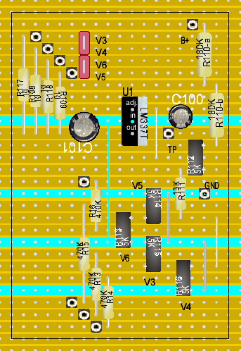
I haven't received all my parts but here is a shot at a veroboard/stripboard design.
I've tried to have the most compact board. I've re-allocated the 470K resistors so I've got less traces to cut.
Any issue having the cathode resistors not too close to the tube sockets?
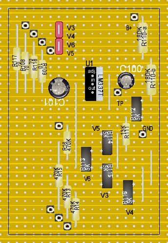
The only PCB hacking are the grid and screen resistors.
I don't know if I can optimise my GND connections...
Please let me know if I need to alter this theoretical design.
I've tried to have the most compact board. I've re-allocated the 470K resistors so I've got less traces to cut.
Any issue having the cathode resistors not too close to the tube sockets?
The only PCB hacking are the grid and screen resistors.
I don't know if I can optimise my GND connections...
Please let me know if I need to alter this theoretical design.
- cedricb
- Posts: 89
- Joined: Mon Jan 28, 2008 4:49 am
![]() by dcgillespie » Sat Nov 05, 2011 10:28 pm
by dcgillespie » Sat Nov 05, 2011 10:28 pm
Cedric -- The only concern you may have is in relocating the 470K grid return resistors to your new board. This will require long leads connected into the grid circuit of each output tube that can promote hum and oscillation problems if not executed carefully. I would possibly use the short possible runs of shielded cable to make those connections, so that no unintended consequences arise from relocating those resistors. Having the 10 ohm cathode resistors on your new board is just fine.
Dave
Dave
- dcgillespie
- KT88
- Posts: 399
- Joined: Sun Mar 08, 2009 5:34 am
- Location: Ball Ground, GA
![]() by cedricb » Sun Nov 06, 2011 4:10 pm
by cedricb » Sun Nov 06, 2011 4:10 pm
@Dave, thanks a lot again for your wealth of knowledges! I'll leave the grid resistors alone in the existent PCB.
What do you recommend for the shielded cable?, so I can use it for linking all the connections between the 2 boards.
What do you recommend for the shielded cable?, so I can use it for linking all the connections between the 2 boards.
- cedricb
- Posts: 89
- Joined: Mon Jan 28, 2008 4:49 am
![]() by dcgillespie » Sun Nov 06, 2011 9:17 pm
by dcgillespie » Sun Nov 06, 2011 9:17 pm
Cedric -- If you are going to leave the 470K grid resistors on the original power amp board modules, then no shielded cable will be required. The connection from the end of these resistors to each of their own adjustment control wiper is of such low impedance that regular hook up wire will be fine. The shielded cable was only going to be required if the resistors were moved off of the actual power amp boards.
Dave
Dave
- dcgillespie
- KT88
- Posts: 399
- Joined: Sun Mar 08, 2009 5:34 am
- Location: Ball Ground, GA
![]() by wicked1 » Fri Jan 20, 2012 2:49 pm
by wicked1 » Fri Jan 20, 2012 2:49 pm
separks wrote:Cedric,
Here is my first stab at modding the EFB for a Rev D. Lots of cuts and jumpers, but doable. It wouldn't be difficult to modify the current layout for the EFB.
http://www.diytube.com/st35/revefb.txt
http://www.diytube.com/st35/revefb.jpg
There may be errors. Also, it hasn't been tested. Note that I have shifted the current sense resistors between Vin and ground.
Shannon
Has anyone tried this implementation yet? I don't have extra room in my case, so need to keep it on-pcb.
-edit- actually, I figured out how to make it fit. I'm using the original sca-35 chassis, so I can build most of the circuit p2p on the back, as Dave did. Then I have room to mount little circuit boards w/ the individual tube adjustments, sort of above each side of the st-35 pcb. I'll post photos when it's done, so that makes sense.
- wicked1
- Posts: 17
- Joined: Sun Jan 27, 2008 7:12 pm
![]() by wicked1 » Sat Jan 21, 2012 11:09 am
by wicked1 » Sat Jan 21, 2012 11:09 am
Can someone explain how to calculate the current out? Show me the equation or something?
I've looked at the datasheet and don't quite get it. After the voltage divider on the EFB schematic I believe there are about 15 volts going to the 337 adjust pin. But, then how do I calculate the current from that? Datasheet expects me to be using the 1.25v from vout to adjust.
Thank you
--edit, I just found a tubecad journal article on using a 337 as CCS, but it did not help. Just like the datasheet, all his examples had "adj" connected to "out".
- wicked1
- Posts: 17
- Joined: Sun Jan 27, 2008 7:12 pm
![]() by dcgillespie » Sat Jan 21, 2012 3:50 pm
by dcgillespie » Sat Jan 21, 2012 3:50 pm
Wicked -- In the EFB(tm) modification, the 337 device is not acting as a constant current source, but rather, as an active voltage regulator who's adj terminal is influenced by the B+ level present. Therefore, you are not setting a current flow that the regulator operates at but rather, you are adjusting the output voltage of the regulator -- which is the bias voltage for the output tubes -- so that the tubes then draw the correct quiescent current as measured through the 5 ohm resistors in the cathode circuit of each channel's output stage.
I hope this provides a better understanding of the regulator's function in the EFB modification. If I can be of any further help, please let me know!
Dave
I hope this provides a better understanding of the regulator's function in the EFB modification. If I can be of any further help, please let me know!
Dave
- dcgillespie
- KT88
- Posts: 399
- Joined: Sun Mar 08, 2009 5:34 am
- Location: Ball Ground, GA
![]() by wicked1 » Sat Jan 21, 2012 5:27 pm
by wicked1 » Sat Jan 21, 2012 5:27 pm
Ok, that clears up the operation of the circuit, but I still don't understand how to calculate the voltage it's set at. Again, all the datasheet examples have adj connected to vout and use that 1.25v between them in the equations.
Obviously, you've done all the work for the sca/st-35, so I don't need this info for this amp. I'm just trying to learn how this all works.
Unless I did something wrong, I get ~15v on the adj. terminal, and don't understand what it's doing w/ that.
The WIKI on these devices says
"An adjustable regulator generates a fixed low nominal voltage between its output and its 'adjust' terminal", which is what all the datasheets have examples for.
How do I apply this info to your circuit and calculate the voltage?
--edit-- Maybe I've got it. If I put a load on the voltage divider, I get much less voltage.. down in the range the regulator wants to see on its adj terminal, and then everything starts to make sense.
--edit2-- No, still don't get it. I understand what the EFB circuit is doing. I don't understand how to calculate what the lm337 is doing.
- wicked1
- Posts: 17
- Joined: Sun Jan 27, 2008 7:12 pm
![]() by dcgillespie » Sun Jan 22, 2012 4:39 pm
by dcgillespie » Sun Jan 22, 2012 4:39 pm
Wicked -- Don't beat yourself up too much over this -- you are not the first person to look at the circuit and either think it's a CC circuit, or finally give up and go "huh?"
To begin with, you need to think of everything in a negative aspect, because the 337 is a negative voltage regulator, as opposed to the more traditional positive regulators folks are used to seeing in the cathode circuit of vacuum tube output stages. Therefore, whereas with a positive regulator, the IN terminal is the most positive point, the ADJ is the least positive point, and the OUT terminal is elevated 1.25 vdc above the ADJ voltage (all relative to ground), with a negative regulator, the IN is the most negative point, the ADJ is the least negative point, and the OUT terminal is elevated 1.25 vdc "above" (more negative in this case) the ADJ voltage (again, all relative to ground). While this aspect of device operation is rather easy to understand, it's the next point that can really hang up those trying to understand the regulator's operation in the EFB modification.
The above description is all relative to "circuit" ground of the basic power supply employed, which in vacuum tube equipment we understand to be B-, or the negative side of the B+ supply as connect to the chassis. With the EFB circuit however, circuit ground of the amplifier is not circuit "ground" of the EFB regulator circuit, in the traditional sense of how a negative voltage regulator is normally connected. When you look carefully at how the voltage regulator operates to the EFB circuit, you will begin to see that in actual fact, the B+ to the output stage (where the voltage divider of the EFB circuit is connected to) is actually "circuit ground" AS FAR AS THE REGULATOR IS CONCERNED. Looked at it in this light then, and understanding that the regulator is a negative voltage device, then B+ represents "circuit ground" of the basic power supply for the regulator, B- represents the most negative point (applied to the IN terminal), the ADJ represents the least negative point, and the OUT terminal operates 1.25 vdc more negative than the ADJ terminal represents -- ALL RELATIVE TO THE OUTPUT STAGE B+ POINT in the amplifier. In other words, as far as the regulator is concerned, it's operating as it would in any other negative voltage regulator application.
Finally, do not make the mistake of believing that the ADJ terminal MUST obtain it's reference voltage from a resistive tap placed across the output of the regulator device for it to operate properly. This is not true. In actual fact, the regulator will regulate the output voltage to 1.25 vdc greater than the absolute value of that at the ADJ terminal -- relative to the regulator supply source's "circuit ground" -- NO MATTER WHERE THE ADJ TERMINAL VOLTAGE IS SUPPLIED FROM.
Applying all of the above then, you can see that the 337 device in the EFB modification operates as a traditional negative voltage regulator (supplying fixed bias in spite of output tube current draw), whose output voltage is modified as appropriate by the prevailing B+ conditions (the "Enhanced" element of EFB). This in turn keeps the output tubes operating on the most linear part of their curve at all times in spite of power supply droop as power output is elevated, and maximum power output is achieved.
As explained in the article, you will find that the bias voltage produced by the EFB modification actually decreases as power output increases -- in direct proportion to the falling B+ as power output increases. This is exactly what should happen -- and is directly opposite of what traditional cathode bias does, where the bias voltage is increased with a falling B+ as power output is increased. In the Dynaco 6BQ5 amplifiers, this causes the output tubes to move way off the linear portion of their operating curve, and explains the very elevated levels of distortion in these amplifiers when the stock bias system is used, and both channels are driven to full power output. By comparison then, converting to fixed bias operation, with a system that will always adjust the quiescent bias to the prevailing B+ conditions at hand, offers significant improvement in these amplifiers than can be quite readily measured and heard.
I hope this answers your questions!
Dave
- dcgillespie
- KT88
- Posts: 399
- Joined: Sun Mar 08, 2009 5:34 am
- Location: Ball Ground, GA
Who is online
Users browsing this forum: No registered users and 2 guests