Have a kit on the way (triode) with a Hammond 372jx PT, 193L choke, and 2xZ565s and a 5ar4 rectifier. Question is for layout on a custom 12x20 plate would the attached layout be acceptable? 5ar4 is the circle in the middle.
Let me know if picture link doesn't work.
Thanks for any advice in advance!
Highlander
http://i871.photobucket.com/albums/ab28 ... layout.jpg
Question on Chassis Layout
18 posts
• Page 1 of 2 • 1, 2
Question on Chassis Layout
![]() by highlander52 » Thu Sep 16, 2010 9:57 pm
by highlander52 » Thu Sep 16, 2010 9:57 pm
Last edited by highlander52 on Sat Sep 18, 2010 12:54 pm, edited 2 times in total.
- highlander52
- Posts: 6
- Joined: Wed Sep 08, 2010 9:21 pm
![]() by Ty_Bower » Thu Sep 16, 2010 10:10 pm
by Ty_Bower » Thu Sep 16, 2010 10:10 pm
First, I'll compliment your choice of the Hammond 300 series power transformer. The bell-ended 193L choke is a fine looking piece of hardware too.
I'm trying hard to follow your ASCII art, but it is late and I am tired. Can you try to upload your images to http://photobucket.com/ and copy & paste the image links here? That usually works very well.
You typically want to try to keep as much space as possible between the PT and OT. The field intensity decreases as the square of the distance, so a one inch separation is sixteen times better than a quarter inch.
You've got the right idea: you want to keep the PT = and the OT ||, or vice versa. If you can manage to get the choke oriented in the third axis, that's gravy.
For what little it's worth, here's my thread when I built my ST35. I had a Z mount PT, so that changes things a bit.
http://www.diytube.com/phpBB2/viewtopic.php?t=1624
"It's a different experience; the noise occlusion, crisp, clear sound, and defined powerful bass. Strong bass does not corrupt the higher frequencies, giving a very different overall feel of the sound, one that is, in my opinion, quite unique."
-

Ty_Bower - KT88
- Posts: 1494
- Joined: Wed Mar 21, 2007 2:50 pm
- Location: Newark, DE
How about now!
![]() by highlander52 » Fri Sep 17, 2010 11:26 pm
by highlander52 » Fri Sep 17, 2010 11:26 pm
Ty, Thanks for the advice, I'd already looked at your build as inspiration...I've uploaded a link to the layout file. Nothing is closer than 2" to anything else so I think I'll be fine but my OPTs are perpendicular to each other and that's what I would like input on. Thanks again.
Highlander
Highlander
- highlander52
- Posts: 6
- Joined: Wed Sep 08, 2010 9:21 pm
![]() by Ty_Bower » Sat Sep 18, 2010 8:36 pm
by Ty_Bower » Sat Sep 18, 2010 8:36 pm
highlander52 wrote:Nothing is closer than 2" to anything else so I think I'll be fine but my OPTs are perpendicular to each other
I see your sketch now. You've got so much space around everything, I can't imagine you will have any kind of magnetic interference. With two inches of separation, I'd expect you can orient anything pretty much any way you want and there shouldn't be problems.
You are going to end up with a rather large chassis, and the visual aesthetics are going to be a bit unconventional. Builders usually prefer to keep both the outputs arranged the same way just for some kind of sense of symmetry. But, it is your amp - feel free to build it any way you like.
I understand your dilemma. My Stereo 35 has no choke, so it seemed pretty obvious to keep all three transformers in a row. The PT goes one way, the OTs go the other, and everyone is happy. With a "four iron" chassis, now you've got the choke to complicate things. I've often seen these kinds of amps laid out with the PT - OT - OT in a row along the back. The choke goes on the side, right in front of the PT. Choke and OTs are all facing the same way, and the PT is turned 90 degrees.
Of course, I also suspect you are trying to keep the OT close to their terminal connections at the board. You could look at the get*set*go layouts for inspiration, because Shannon used a similar terminal layout on that board (power in the back, inputs on the front, finals out the sides). Then again, many of the GSG builds have the choke hidden away under the chassis. You don't really want to do that with a 193J.
Keep thinking... I'm sure you'll find the right solution.
"It's a different experience; the noise occlusion, crisp, clear sound, and defined powerful bass. Strong bass does not corrupt the higher frequencies, giving a very different overall feel of the sound, one that is, in my opinion, quite unique."
-
Ty_Bower - KT88
- Posts: 1494
- Joined: Wed Mar 21, 2007 2:50 pm
- Location: Newark, DE
New layout for discussion
![]() by highlander52 » Wed Sep 22, 2010 9:30 pm
by highlander52 » Wed Sep 22, 2010 9:30 pm
Got a new layout...used Front Panel Designer to create a layout and then laid out the parts. Am concerned now about proximity of 5ar4 to PT. New size is 10.25x17.75, much more manageable. Showed it to my wife and she said, "Does it have to be that big!" First time I ever heard her say that!


- highlander52
- Posts: 6
- Joined: Wed Sep 08, 2010 9:21 pm
![]() by Ty_Bower » Thu Sep 23, 2010 8:00 am
by Ty_Bower » Thu Sep 23, 2010 8:00 am
That looks pretty good to me. You might consider turning the 193L ninety degrees to minimize any interaction with the power transformer. It's so far away from the outputs, it won't matter if it's in the same orientation as them.
"It's a different experience; the noise occlusion, crisp, clear sound, and defined powerful bass. Strong bass does not corrupt the higher frequencies, giving a very different overall feel of the sound, one that is, in my opinion, quite unique."
-
Ty_Bower - KT88
- Posts: 1494
- Joined: Wed Mar 21, 2007 2:50 pm
- Location: Newark, DE
![]() by TomMcNally » Thu Sep 23, 2010 9:06 am
by TomMcNally » Thu Sep 23, 2010 9:06 am
The only comment I would make is that with the transformers
so far from the terminal blocks, instead of being right next to
the EL-84's ... you are going to have to extend all of your
primary leads. I've built a bunch of ST-35's, mostly on
12x8x3 chassis, or on the Triode Stainless Steel chassis.
I'd suggest putting the output transformers on each end,
and the choke and power transformer in the center.
-

TomMcNally - Darling du Jour
- Posts: 2729
- Joined: Sat Nov 19, 2005 2:19 pm
- Location: Northfield, NJ
![]() by Ty_Bower » Thu Sep 23, 2010 9:31 am
by Ty_Bower » Thu Sep 23, 2010 9:31 am
Here's a suggestion that might raise an eyebrow - why not skip the choke on this project? Save the 193L for that single ended project somewhere down the road.
Shannon's DIY ST35 board already has quite a bit of power supply filtering. Push/pull output stages have good power supply rejection ratios. I think the few people who bothered to put a choke in their ST35 used something much smaller (like a Dynaco C354 or a Triad C-24X), and even then they didn't report much (if any) difference.
If you take out the choke, arranging the rest should be simple.
"It's a different experience; the noise occlusion, crisp, clear sound, and defined powerful bass. Strong bass does not corrupt the higher frequencies, giving a very different overall feel of the sound, one that is, in my opinion, quite unique."
-
Ty_Bower - KT88
- Posts: 1494
- Joined: Wed Mar 21, 2007 2:50 pm
- Location: Newark, DE
![]() by elbinster » Thu Sep 23, 2010 11:20 am
by elbinster » Thu Sep 23, 2010 11:20 am
I built Shannon's ST35 as my first tube project and had all kinds of crazy thoughts about parts interacting with eachother.
Now that it's built
I can't get it to hum, buzz, or any other onomatopoetic word you can think of. I can put my ear right up to the speaker and not pick up even a hint of hum, only the gentle hiss of the noise floor. I would suggest laying it out how your wife likes it, and then tweak orientations and distances to reduce the chance of problems.
Also, Shannon's design is very symmetrical, so consider laying out the chassis in a similar way to reduce any chance of one channel making noise, and the other not (more annoying, to me, than both channels making noise).
As a general rule of thumb. If you aren't sure if one thing will interact with another, make sure they're 90 degrees apart (orthogonal to eachother), and they'll play nice. That goes for transformer orientation and wiring. I.e. if you have to run a signal line over a power line, make sure they cross at a 90 degree angle.
-
elbinster - Posts: 81
- Joined: Sat Dec 12, 2009 3:45 pm
- Location: Springfield, VA


![]() by EWBrown » Thu Sep 23, 2010 10:45 pm
by EWBrown » Thu Sep 23, 2010 10:45 pm
Another approach, especiallywith Rev C and D boards, is to locate the Output Trannies at the ends of the circuit board, this allows for short leads and neat, direct connections. THis works best with long chassis, I'built up a couple of ST35s on 10X 17 inch chassis this way, and even though they were definitely oversized, the results were excellent.
The power trannie and choke can mount behindf the board, and this will still give a reasonably symmetrical layout and appearance.
WIth all of the extra "real estate" on the top of the chassis, the input and output connections, and fuse, power switch and AC power inlet can all be top-mounted, very neatlhy.
/ed B
Real Radios Glow in the Dark
-

EWBrown - Insulator & Iron Magnate
- Posts: 6389
- Joined: Wed Mar 19, 2003 6:03 am
- Location: Now located in Clay County, NC !
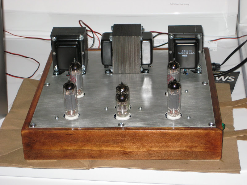
Its alive!!!
![]() by highlander52 » Fri Nov 12, 2010 8:36 pm
by highlander52 » Fri Nov 12, 2010 8:36 pm
WOW is all I can say...It runs and is dead quiet. Set bias and it sounds phenomenal even driving POC JVC minisystem speakers. Still haven't finished the wooden pieces that will hold all the good bits. Many thanks to Shannon and all on this board who, whether you knew it or not, have posted about this amp...I think I've literally read every post and would have been lost without them. Thanks again all!
I haven't hooked up the panel meters yet...I think they should read pin 3 for cathode current and pin 7 for plate voltage.
Highlander

I haven't hooked up the panel meters yet...I think they should read pin 3 for cathode current and pin 7 for plate voltage.
Highlander
- highlander52
- Posts: 6
- Joined: Wed Sep 08, 2010 9:21 pm
Oops...forgot the other side
![]() by highlander52 » Fri Nov 12, 2010 8:43 pm
by highlander52 » Fri Nov 12, 2010 8:43 pm
Here is the other side, notice all the loose wires for the panel meters...probably should have listened to that little voice in my head that said, "Make it simple", but I just can't!

- highlander52
- Posts: 6
- Joined: Wed Sep 08, 2010 9:21 pm
![]() by 77seriesIII » Sun Nov 21, 2010 1:50 pm
by 77seriesIII » Sun Nov 21, 2010 1:50 pm
a question for someone, I need to drill some holes and use the hole punches. Anyway, does anyone have a 1:1 scale that I can print and tape to the chassis surface? I am only concerned with cutting the holes to mount the PCB.
Thanks
erick
Thanks
erick
- 77seriesIII
- Posts: 174
- Joined: Sat Nov 10, 2007 3:48 pm
- Location: Germany/USA
![]() by TomMcNally » Sun Nov 21, 2010 2:34 pm
by TomMcNally » Sun Nov 21, 2010 2:34 pm
Erick -
The best way is to actually use the board for a template,
but I assume you already built the board?
Did you look at the drawings in the manual?
It's in the first message in this topic of the forum.
I have a blank one, I could photocopy and mail you.
I don't know if a scan would be actual size?
I like templates!
... tom
-
TomMcNally - Darling du Jour
- Posts: 2729
- Joined: Sat Nov 19, 2005 2:19 pm
- Location: Northfield, NJ
18 posts
• Page 1 of 2 • 1, 2
Who is online
Users browsing this forum: No registered users and 14 guests