Intermittent Thump Issue with with my new ST35 board
44 posts
• Page 2 of 3 • 1, 2, 3
I built the amp per the instructions. I bought the ST35 Driver board Rev D. The only capacitor on the input is a 33pF to ground. The instructions only have me install an input resistor. The Antek output transformer link follows: https://www.antekinc.com/pdf/AT-020L.pdf . Apparently they were lying through their teeth. The specs make it look like a very good transformer. I wish they would provide an example tube amp schematic for that response. I have used their power transformers with no problem, they are high quality at very low price. Recently they started offering nice black can covers for their transformers and they make the toroid transformers look much better if mounted to the top of the chassis. They have 4 different output transformers and the 20W version had the best specs. This was my first experience with toroid output transformers. There is a sister company to Antek called www.par-metal.com They have nice enclosures at a low price. Both rack mount and table top units.
- HiFiGuy
- Posts: 35
- Joined: Fri Feb 05, 2010 9:37 pm
Re: Update
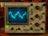
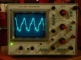
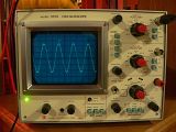
HiFiGuy wrote:I started the amplifier with all Antek Iron. When all was finished I hooked it up to my scope and at full power (5 Watts) the bandwidth was 20 - 8 KHz. If I tried any higher power the waveform would get badly distorted.
Interesting. I used Hammond 1620 output transformers on my first DIYtube Stereo 35. I'll admit I never checked the high frequency extension, but for more than a few watts the 1620 got weird below 40 Hz or so.


"It's a different experience; the noise occlusion, crisp, clear sound, and defined powerful bass. Strong bass does not corrupt the higher frequencies, giving a very different overall feel of the sound, one that is, in my opinion, quite unique."
-

Ty_Bower - KT88
- Posts: 1494
- Joined: Wed Mar 21, 2007 2:50 pm
- Location: Newark, DE
Transformers
In looking for output iron the specs are always lacking on the low side. I can't really hear anything above 15 Khz and I am only 31!! My Frequency response is only getting worse as I get older. The first frequencies to go in your ear are the higher ones. My dad is a general contractor and I help him when Im out of school so I am no stranger to loud machinery (Jackhammer, Equipment Engines, Nail Guns). I try to use earplugs as much as possible but its impossible to know when someone is about to start a generator or start jackhammering.
- HiFiGuy
- Posts: 35
- Joined: Fri Feb 05, 2010 9:37 pm
Re: Transformers
HiFiGuy wrote:I try to use earplugs as much as possible...
Earplugs are your friend. I always keep a set in my jacket pocket. I use them at work, when I'm mowing the lawn, and most importantly when I'm drilling holes in a chassis for a new tube amp.
"It's a different experience; the noise occlusion, crisp, clear sound, and defined powerful bass. Strong bass does not corrupt the higher frequencies, giving a very different overall feel of the sound, one that is, in my opinion, quite unique."
-

Ty_Bower - KT88
- Posts: 1494
- Joined: Wed Mar 21, 2007 2:50 pm
- Location: Newark, DE
Hifi --
You're right, the specs are lacking, but then they usually are with transformers. In any event, the Antek transformer has significant differences as compared to the original device. Besides being over 25% greater in primary impedance, most importantly, the screen tap is well off the required % for UL operation of 6BQ5 tubes. This is not insignificant, but unfortunately, it is very common with aftermarket transformer manufacturers, who think that a 40% tap is the end all be all for all tubes. Nothing could be further from the truth. For many it is, but the 6V6/EL84 family of tubes perform very poorly at that percent. No doubt this is a major reason your power output was reduced. Undoubtedly, anyone who has measured an ST-35 clone using Hammond iron has been equally disappointed, as they use the same tap % for all of their transformers as well. I can only assume that if the Dynaclone transformer is an exact copy of the original, then it's tapping point is correct.
The effect of using an OPT with a greater primary impedance is basically the same as underloading the amp by placing a 10 ohm speaker on the 8 ohm tap. While that may be good for speaker damping, it works against LF amplifier damping. That was the first strike against LF stability -- as well as reducing power output. The second strike was using coupling caps that were 120% greater than the original value. The third and final strike is the design of the diytube board itself. The diy board uses separate cathode resistors, and massive bypass caps. While the separate resistors do allow for independent bias adjustment which is good for usable output transformer LF peformance, separating the cathodes also eliminates the ability for the stage to self balance itself to near dc signals. This is important, as it is at those kinds of frequencies, where LF instability resides. Add to that, the RC combination for each cathode with the new board is 22 times that of the original design. The combination of these two things has changed the ultra-low frequency characteristics of the output stage significantly.
Using the Dynaclone transformer surely improved matters a lot. Toroids have never been known for their ultra-low frequency performance. But if you are using the equivalent of the original feedback factor (for 8 ohms the FB resistor would need to be 18,708 ohms), and if the Dynaclone transformer has the same ultra-low frequency characteristics as the original transformers, then the combination of the increased coupling cap values along with the new treatment of the cathodes is still a major invitation to LF instability. Using the original value coupling caps could return respectable stability, but it's doubtful that it would be as stable at low frequencies as the original design was. To mimic the original RC factor in the cathode circuit of the output stage, the cathode bypass caps for the new board would need to be around 22 uF each, so you can see how much greater the 470 uF of the new arrangement represents.
One way to check for ultra-low frequency stability is to pulse the input of the amplifier with a low voltage DC source of about .25 vdc, and watch the cone of your speaker. It should react precisely to the pulse with no signs of settling after waves present. Your scope can help watch for this as well. If they are still present, I would reduce the bypass cap values to the point where a stable response to the pulse is be obtained.
Dave
[/i]
- dcgillespie
- KT88
- Posts: 399
- Joined: Sun Mar 08, 2009 5:34 am
- Location: Ball Ground, GA
The cathode bypass cap value is much less of a contributor to the low frequency stability (or instability) than the main coupling caps in my experience. Indeed, I think oversized coupling caps in feedback amps can be a source of many gremlins.
This is where it is handy to have a function generator than can go down to milliHertz and just scope the output of the amp while moving from 40Hz to DC. It'll get messy real fast. My goal when designing is to keep the gain from increasing even if the output transformer can't do a clean sine wave (usually below 5Hz). This is akin to a high frequency 'ringing' at the leading edge of a 10kHz square wave. Obviously not everyone has the gear to do this, so less feedback or smaller coupling caps is the solution when working with cheaper outputs.
Shannon
-

Shannon Parks - Site Admin
- Posts: 3764
- Joined: Tue Mar 18, 2003 5:40 pm
- Location: Poulsbo, Washington
Thanks Shannon --
I agree that the coupling cap has greater influence on LF stability, but in this case, the combination of separating the two output tube cathodes and then using bypass caps of such greater value is not insignificant either. My suggestion to reduce the size of the cathode bypass caps was only if instability persisted even after the proper coupling cap values had been installed. Of course, reducing the feedback would also help in this matter, but at the expense of other qualities.
It's my understanding that after the rectifier snubbers were removed, but while the larger coupling caps were still installed, HiFi said he found that his woofers were breathing back and forth, indicating LF instability.
Thanks for your input.
Dave
- dcgillespie
- KT88
- Posts: 399
- Joined: Sun Mar 08, 2009 5:34 am
- Location: Ball Ground, GA
Snubbers
The snubber network added to the problem. I use to get the drop out about 5 times an hour. Without them I get the drop out 2 per 3 hours. I am going to install some WIMA coupling caps today after school and give it a listen. Hopefully this will be the last time I will need to open the amp up.
- HiFiGuy
- Posts: 35
- Joined: Fri Feb 05, 2010 9:37 pm
Update
I have replaced my coupling caps with .1uf units, I am still getting the speaker breathing problem. This is my first PCB tube amplifier and I am tempted to recreate the circuit using the existing chassis and point to point wiring. The board is currently exactly as the schematic shows it in the manual that came with my board.
- HiFiGuy
- Posts: 35
- Joined: Fri Feb 05, 2010 9:37 pm
dcgillespie wrote:Negative Feedback is simple in concept, but very complex to apply correctly. It is at the root of your issue, as if you disconnected the NFB loop, the breathing would go away.
Have you tried temporarily disconnecting the NFB loop, as Dave suggested? I'm not saying you should plan to run it that way, but we might learn something from the test.
"It's a different experience; the noise occlusion, crisp, clear sound, and defined powerful bass. Strong bass does not corrupt the higher frequencies, giving a very different overall feel of the sound, one that is, in my opinion, quite unique."
-

Ty_Bower - KT88
- Posts: 1494
- Joined: Wed Mar 21, 2007 2:50 pm
- Location: Newark, DE
The fact that the snubber network was a factor that seems to have been directly related to the condition might suggest that the problem is very close to the rectifiers if not one of them. Perhaps a leaky rectifier is opening for a second once it gets hot. Use some cold spray on each one and watch to see how quickly the frost melts. If one clears off more quickly than the other then I'd suspect a hot diode breaking down. Or, conversely, if one is having trouble conducting it may stay colder and the cold spray may actually create a dropout. You might find it immediately.
Headed for Tishomingo to sing in a can...
-

20to20 - KT88
- Posts: 566
- Joined: Wed Apr 21, 2010 1:48 pm
- Location: W-S, NC
OK. Now it's officially getting weird. Next step is to pull the driver tubes and see if the breathing continues. It would also be helpful to know more about the breathing. Can you estimate the Hz? Is it barely visible or quite significant? Are both channels doing it? In unison? With the driver tubes removed, it would be hard to imagine what would cause the unit to oscillate in that condition, short of something mis-wired or crossed between the channels. Is the PS bypass cap for the driver stage in good condition and well grounded? The devil is always in the details, and to go further, we're going to need more.
Dave
Dave
- dcgillespie
- KT88
- Posts: 399
- Joined: Sun Mar 08, 2009 5:34 am
- Location: Ball Ground, GA
An added thought about using the cold spray on the rectifiers. If one of the rectifiers is the problem, it may show this as a faster or slower speaker breathing when the cold spray is applied. If you don't have a can of chill spray, you can use a can of dust-off turned upside down. The propellant is the same stuff
Headed for Tishomingo to sing in a can...
-

20to20 - KT88
- Posts: 566
- Joined: Wed Apr 21, 2010 1:48 pm
- Location: W-S, NC
44 posts
• Page 2 of 3 • 1, 2, 3
Who is online
Users browsing this forum: No registered users and 34 guests
