Built-in bias meter
14 posts
• Page 1 of 1
Built-in bias meter
![]() by Thor61 » Thu Mar 04, 2010 4:27 pm
by Thor61 » Thu Mar 04, 2010 4:27 pm
Has anyone implemented or constructed there amp with a analog bias meter built in ? If so what would be fool proof way to wire one to the "ST35" pcb ? I had thought of using a selector sw and off board trimmers. The reason for my inquire is to make adjustment safer easier ect... Also they look good to !
- Thor61
- Posts: 50
- Joined: Sat Feb 13, 2010 9:31 pm
![]() by mesherm » Thu Mar 04, 2010 6:01 pm
by mesherm » Thu Mar 04, 2010 6:01 pm
Yes, I have built a few. Mostly on my SE amps though where a SPDT switch selects which tube I'm adjusting. My SE amps all use fixed bias.
http://home.earthlink.net/~mikesherman/images/300B-front.jpg
There is one supplier on ebay that sells 0 to 1 VDC analog meters. Finding one of them is the key. Then all you need to add is a 10 ohm cathode resistor, selector switch, and bias pots. Although I used the larger 10 turn wirewound pots on that 300B amp I prefer to use 20 turn trimmers that fit into a separate housing for panel mounting. They take up less space and have lots of adjustment range.
Mike's N-1 Rule: When looking for N number of components to finish a job, you have a 95% chance of only finding N-1 of them.
-

mesherm - KT88
- Posts: 1232
- Joined: Fri Aug 27, 2004 10:33 pm
- Location: Alvin Texas
![]() by Thor61 » Thu Mar 04, 2010 6:39 pm
by Thor61 » Thu Mar 04, 2010 6:39 pm
Very nice work ! I think meters give diy amps a more hi-tech look and function. Here is a link to the trimmers I plan to use > http://webtronics.stores.yahoo.net/102w10tupot3.html
- Thor61
- Posts: 50
- Joined: Sat Feb 13, 2010 9:31 pm
![]() by evsentry3 » Thu Mar 04, 2010 7:06 pm
by evsentry3 » Thu Mar 04, 2010 7:06 pm
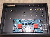
Another, and simplier option, is to install pin jacks on top your chassis with short jumpers wired underneath to the test points.
Then flip the pots over to the opposite side of the PC board...so they mount to the top side. Drill small holes on the top of the chassis to expose the pot screw. And if you've got the spacing right, viola!
Grab your VOM and a small screwdriver and do your business all without disturbing the amp from it's position. Works well!!
Mark
PS...found pictures of top and bottom and added them to my Pictures section on the forum here. Helps explain over just the words.
Last edited by evsentry3 on Thu Mar 04, 2010 7:33 pm, edited 1 time in total.
- evsentry3
- Posts: 32
- Joined: Mon May 03, 2004 1:18 pm
- Location: Knoxville Tennessee
![]() by Ty_Bower » Thu Mar 04, 2010 7:19 pm
by Ty_Bower » Thu Mar 04, 2010 7:19 pm
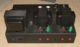
evsentry3 wrote:Then flip the pots over to the opposite side of the PC board...so they mount to the top side. Drill small holes on the top of the chassis to expose the pot screw. And if you've got the spacing right, viola!
Yup. Here's a photo which shows the bias pots pretty well.

"It's a different experience; the noise occlusion, crisp, clear sound, and defined powerful bass. Strong bass does not corrupt the higher frequencies, giving a very different overall feel of the sound, one that is, in my opinion, quite unique."
-

Ty_Bower - KT88
- Posts: 1494
- Joined: Wed Mar 21, 2007 2:50 pm
- Location: Newark, DE
![]() by Thor61 » Thu Mar 04, 2010 7:26 pm
by Thor61 » Thu Mar 04, 2010 7:26 pm
I'm thinking of using this> Analog Bias and High Voltage Monitor @ https://taweber.powweb.com/store/modkits.htm cant beat the price $22.00 ! If installing pin jacks on top your chassis with short jumpers, would it be best to sandwich the wires between enclosure and pcb or sling them from below to pin jacks ? Probably sounds like a crazy question but I don't understand much about proper wire routing and picking up hum ect... PS: This is my first real tube amp project, along with a million questions I'm really hoping things turn out well !
- Thor61
- Posts: 50
- Joined: Sat Feb 13, 2010 9:31 pm
![]() by Ty_Bower » Thu Mar 04, 2010 8:20 pm
by Ty_Bower » Thu Mar 04, 2010 8:20 pm
I'd mount the test jacks on the rear skirt of the chassis.

"It's a different experience; the noise occlusion, crisp, clear sound, and defined powerful bass. Strong bass does not corrupt the higher frequencies, giving a very different overall feel of the sound, one that is, in my opinion, quite unique."
-
Ty_Bower - KT88
- Posts: 1494
- Joined: Wed Mar 21, 2007 2:50 pm
- Location: Newark, DE
![]() by Ty_Bower » Thu Mar 04, 2010 9:10 pm
by Ty_Bower » Thu Mar 04, 2010 9:10 pm
Sorry about the pic. Photobucket is being weird tonight. It'll show up in a day or two. I wouldn't route wiring between the chassis top and the circuit board, but that's just me. It seems like it would be so much easier to just access the circuit board from the underside.
I really like the Makizou clones, but they're not for everyone. There's no deep bass at all, and they can't handle much power. Despite the shortcomings, I think there is something special about them. They were pretty cheap to build, so I'd recommend them to anyone if you enjoy working with wood. I'm hoping someday maybe I'll build some bigger six foot tall double mouth back loaded horn things.
I really like the Makizou clones, but they're not for everyone. There's no deep bass at all, and they can't handle much power. Despite the shortcomings, I think there is something special about them. They were pretty cheap to build, so I'd recommend them to anyone if you enjoy working with wood. I'm hoping someday maybe I'll build some bigger six foot tall double mouth back loaded horn things.
"It's a different experience; the noise occlusion, crisp, clear sound, and defined powerful bass. Strong bass does not corrupt the higher frequencies, giving a very different overall feel of the sound, one that is, in my opinion, quite unique."
-
Ty_Bower - KT88
- Posts: 1494
- Joined: Wed Mar 21, 2007 2:50 pm
- Location: Newark, DE
![]() by Thor61 » Thu Mar 04, 2010 9:56 pm
by Thor61 » Thu Mar 04, 2010 9:56 pm
Ty, That amp looks really good ! I could not help noticing the slots cut in the front top of the chassis , what kind of paint did you use for touch-up ? I have several scratches that will need attention and/or repair in my Hammond enclosure.
- Thor61
- Posts: 50
- Joined: Sat Feb 13, 2010 9:31 pm
![]() by Ty_Bower » Fri Mar 05, 2010 6:41 am
by Ty_Bower » Fri Mar 05, 2010 6:41 am
I didn't build the amp with the slots in the top, but I believe it is just a powder coat finish. I did assemble another amp starting from a bare aluminum chassis. I took the punched & drilled chassis to the powdercoaters where they coated it wrinkle black. It's a fantastic, extremely durable finish. They charged me about twenty bucks to do the job. The powder is applied to the chassis electrostatically and then the thing is cured in an oven. If you drill all the holes before you get it coated, you won't be able to see a speck of aluminum anywhere.
Wish I had a better picture, but I guess this will have to do. This isn't a pre-painted Hammond chassis - it was bare aluminum when I started.
Wish I had a better picture, but I guess this will have to do. This isn't a pre-painted Hammond chassis - it was bare aluminum when I started.

"It's a different experience; the noise occlusion, crisp, clear sound, and defined powerful bass. Strong bass does not corrupt the higher frequencies, giving a very different overall feel of the sound, one that is, in my opinion, quite unique."
-
Ty_Bower - KT88
- Posts: 1494
- Joined: Wed Mar 21, 2007 2:50 pm
- Location: Newark, DE
![]() by Thor61 » Fri Mar 05, 2010 9:18 am
by Thor61 » Fri Mar 05, 2010 9:18 am
Ty, Your pictures look quite good for this end ! Is that a Bud Industries enclosure ? If I were to do all this over again Bud has a 14 x 10 x 3 alum chassis I'd use. With the Hammond its like trying to put 10 lbs of *#@! in a 5 lbs box ! Very nice work !
- Thor61
- Posts: 50
- Joined: Sat Feb 13, 2010 9:31 pm
![]() by mesherm » Fri Mar 05, 2010 1:05 pm
by mesherm » Fri Mar 05, 2010 1:05 pm
http://cgi.ebay.com/NEW-DC-0-1V-Analog-Votage-Panel-Meter_W0QQitemZ350260585206QQcmdZViewItemQQptZLH_DefaultDomain_0?hash=item518d2862f6
This is the meter I use on my amps.
Using a voltmeter you don't have to put the meter in series with the tube(s) being measured as you would if you use an ammeter.
This is the meter I use on my amps.
Using a voltmeter you don't have to put the meter in series with the tube(s) being measured as you would if you use an ammeter.
Mike's N-1 Rule: When looking for N number of components to finish a job, you have a 95% chance of only finding N-1 of them.
-
mesherm - KT88
- Posts: 1232
- Joined: Fri Aug 27, 2004 10:33 pm
- Location: Alvin Texas
14 posts
• Page 1 of 1
Who is online
Users browsing this forum: No registered users and 15 guests