Ok, so I'm a newb when it comes to tube amps, and hifi audio in general, but I've been taken by the stories here about how fantastic they sound. So I dove in and got most of the generic electronics, but have started to run into questions my electronics training cannot answer.
When it comes to the aesthetics of the build... I didn't want to buy a pre-made chassis (no money left in the budget). Is there a reason to use a non-magnetic metal like aluminum? Would a block of iron or nickel or copper cause some kind of unwanted magnetic interaction or hum?
Also, would the experts here advise against adjusting the location of the tubes? Would extending the ports to different locations on the chassis cause problems?
I've read a few threads here that suggest mounting the output transformers as far away from each other as possible.
I'm all over the place here, but any suggestions or tips would go a long way.
New ST35 build
19 posts
• Page 1 of 2 • 1, 2
New ST35 build
![]() by elbinster » Sat Dec 12, 2009 9:34 pm
by elbinster » Sat Dec 12, 2009 9:34 pm
-

elbinster - Posts: 81
- Joined: Sat Dec 12, 2009 3:45 pm
- Location: Springfield, VA
Re: New ST35 build
![]() by Ty_Bower » Sun Dec 13, 2009 12:50 pm
by Ty_Bower » Sun Dec 13, 2009 12:50 pm
elbinster wrote:Ok, so I'm a newb when it comes to tube amps...
Is there a reason to use a non-magnetic metal like aluminum? Would a block of iron or nickel or copper cause some kind of unwanted magnetic interaction or hum?
Also, would the experts here advise against adjusting the location of the tubes? Would extending the ports to different locations on the chassis cause problems?
I've read a few threads here that suggest mounting the output transformers as far away from each other as possible.
Welcome to diytube!
I prefer to use aluminum because it is very easy to work, even with simple tools (hand drill, circular saw, etc). I've seen lots of examples of steel and copper chassis, and they work well too. I think you are free to use whatever you please for the chassis - your metalworking skills are the limit.
I would discourage trying to relocate the sockets off the chassis, although I know it has been done with the ST35 board. One person even went with all octal sockets, if I recall correctly. Part of the beauty of the circuit board design is that it eliminates a lot of potential for user error. Adding bits of wiring from the board to chassis mount sockets might also introduce unwanted oscillations.
The more space on top of the chassis, the better. You definitely want to keep the power transformer away from the output transformers. Try to keep the transformer laminations at 90 degree angles, if possible. You don't want the PT lams parallel to the OPT lams. Given the limited number of possible combinations, the OPT will end up oriented in the same direction. That's OK - crosstalk between them will be minimal and inaudible. I've read that it is preferred to mount the OPT with their end bells facing each other for minimal crosstalk.
The wiring under the chassis will probably play a bigger role in unwanted hum, rather than the position of the transformers.
Good luck! Have fun with the project.
"It's a different experience; the noise occlusion, crisp, clear sound, and defined powerful bass. Strong bass does not corrupt the higher frequencies, giving a very different overall feel of the sound, one that is, in my opinion, quite unique."
-

Ty_Bower - KT88
- Posts: 1494
- Joined: Wed Mar 21, 2007 2:50 pm
- Location: Newark, DE
![]() by elbinster » Wed Dec 16, 2009 9:53 am
by elbinster » Wed Dec 16, 2009 9:53 am
Thanks for getting back to me. It seems like a good idea to have my first build be by-the-book, and play around more when I have some knowledge built up. In the spirit of this forum, my best bet would be to get it working, experiment a bit and report back the results. I look forward to diving in once the parts start showing up!
-
elbinster - Posts: 81
- Joined: Sat Dec 12, 2009 3:45 pm
- Location: Springfield, VA
![]() by mesherm » Thu Dec 17, 2009 5:36 pm
by mesherm » Thu Dec 17, 2009 5:36 pm
Almost any push pull EL84 with good quality output transformers would be a good starter amp as it is not overly expensive to build, has a reasonable amount of power and will probably sound quite good.
You might regret skimping on the chassis after you have finished building it though. I use Hammond steel chassis with the black powder coat the most. In some ways steel is easier for me to to work with than aluminum.
Brass and copper are very expensive. I had a chassis made out of 0.093 inch brass 12" x 18" x 3" and the metal alone was $200 plus another $120. Avoid stainless steel chassis unless your getting it pre-drilled for you.
Mike's N-1 Rule: When looking for N number of components to finish a job, you have a 95% chance of only finding N-1 of them.
-

mesherm - KT88
- Posts: 1232
- Joined: Fri Aug 27, 2004 10:33 pm
- Location: Alvin Texas
Pictures
![]() by elbinster » Fri Jan 15, 2010 5:15 pm
by elbinster » Fri Jan 15, 2010 5:15 pm
I agree that skimping on the chassis would be regretted. Once it's working, it's hard to tear it down and put it in a nicer looking box. At the last minute, I got some sense and realized I don't have the equipment or skill to machine anything more solid than aluminum and wood (and even that was a stretch). I've gotten most of the chassis done. It's a matter of staining/sealing the wood. Once the trannys show up, I'll be in business!
Here's a picture of the finished board. Two years of professional soldering made this the easiest part of the project.
If anyone notices anything wrong, please let me know.
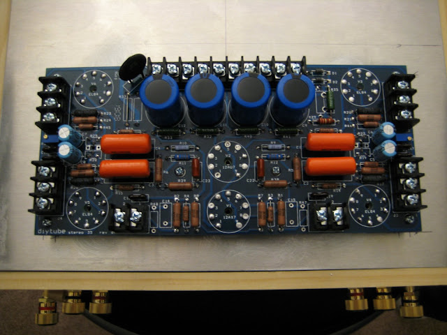
Thanks, I can't wait to start experimenting and enjoying!
Here's a picture of the finished board. Two years of professional soldering made this the easiest part of the project.
If anyone notices anything wrong, please let me know.
Thanks, I can't wait to start experimenting and enjoying!
-
elbinster - Posts: 81
- Joined: Sat Dec 12, 2009 3:45 pm
- Location: Springfield, VA
![]() by mesherm » Fri Jan 15, 2010 6:20 pm
by mesherm » Fri Jan 15, 2010 6:20 pm
The chassis or case doesn't always even have to be metal or wood.
http://home.earthlink.net/~mikesherman/images/top.jpg
http://home.earthlink.net/~mikesherman/images/top.jpg
Mike's N-1 Rule: When looking for N number of components to finish a job, you have a 95% chance of only finding N-1 of them.
-
mesherm - KT88
- Posts: 1232
- Joined: Fri Aug 27, 2004 10:33 pm
- Location: Alvin Texas

![]() by elbinster » Thu Jan 21, 2010 1:11 pm
by elbinster » Thu Jan 21, 2010 1:11 pm
Mike, That case is pretty damn rad! I was certainly humbled by my experience building a simple chassis, and was grateful at how forgiving wood and aluminum can be. As I said, once I get some kind of precision tooling equipment, I'll try to put something together that's half that cool. How well does the acrylic hold up to the heat from the tubes?
Speaking of heat from the tubes, I finally got my trannys, and wired up the amp! Got it running last night without blowing a single fuse or capacitor (though I'm sure I lost a few years to stress). I'm still waiting on a painfully slow shipment from ebay to provide me with a pair of dynaco A25s too plug into this beast. But the speakers I have gave me a taste of what ~17 watts/channel sounds like.
At first I had a good amount of hum coming from the speakers, but I didn't worry, since my test bed consisted of a washing machine squeezed between a heater and old fridge. Once I got the biases set and moved it to a more reasonable audio location the 774 was humming more than the speakers were. I'll have pics to post once I get out of work.
On another note, the instructions say to tie the ground to the chassis, which seems normal, except that very few plugs in my house have a ground pin. At that point, it seems all I'm doing is tying my chassis to the rest of the chassisseses on the same plug. Doesn't seem to be a benefit there, and may cause problem if a short were to exist somewhere. Would there be a reason I'd want to keep the chassis plugged into that ground, or should I just tape up that wire?
Thanks for the help, and kuddos to Shannon for laying out a truly awesome PCB.
-
elbinster - Posts: 81
- Joined: Sat Dec 12, 2009 3:45 pm
- Location: Springfield, VA
![]() by mesherm » Thu Jan 21, 2010 2:11 pm
by mesherm » Thu Jan 21, 2010 2:11 pm
I normally keep amp ground separate from the chassis but then ground the chassis to the 115 volt AC ground. Doing this requires that your input RCA jacks have insulated mounting washers or be mounted on an insulated plate of some kind.
The original ST35 and ST70 only had two wire AC cords on them but they both had a grounded chassis.
Sometimes on preamps I will add a toggle switch in back that connects the amp ground to the chassis/AC ground. This helps with possible ground loop problems.
Obviously my clear plastic case was not grounded but I DID connect all three transformer and the two fan housings together and had those connected to AC ground.
Mike's N-1 Rule: When looking for N number of components to finish a job, you have a 95% chance of only finding N-1 of them.
-
mesherm - KT88
- Posts: 1232
- Joined: Fri Aug 27, 2004 10:33 pm
- Location: Alvin Texas
![]() by ioginy » Sun Jan 24, 2010 1:54 pm
by ioginy » Sun Jan 24, 2010 1:54 pm
IN regard to that acrylic chassis of yours. I am building a guitar amp with an acrylic chassis and I am having a little difficulty with the grounding scheme of things. My main problem is, well, everything to do with the ground.
Here is my ground scenario and I'll let you run with it.
-I have bussed together the tone stack, volume and input grounds.
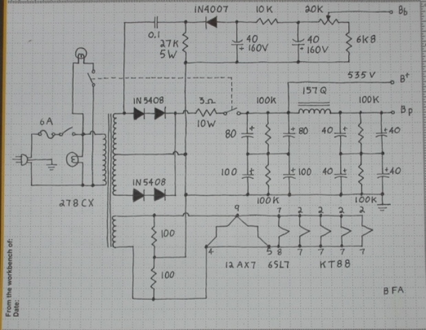
-The my secondary center tap as well as my 6.3v center tap are grounded with a bias circuit. (refer to schem at bottom)
So, now I have 7 ground wires stick straight up in the air (not including the safety ground from the plug) and I am at a stall.
Ground wires are as follows
- input/tone stack
- bias control/center taps
- first filter cap before standby switch
- second, third and fourth filter caps bussed together
- preamp tube cathode bias grounds
- speaker jack ground
- power tube cathodes with 10ohm resistors for bias reading
Oh, I should mention that this is based off a fender deluxe ab763 circuit.
The rest of the filtering in this schematic is not in mine, I am just using the bias part.
Here is my ground scenario and I'll let you run with it.
-I have bussed together the tone stack, volume and input grounds.
-The my secondary center tap as well as my 6.3v center tap are grounded with a bias circuit. (refer to schem at bottom)
So, now I have 7 ground wires stick straight up in the air (not including the safety ground from the plug) and I am at a stall.
Ground wires are as follows
- input/tone stack
- bias control/center taps
- first filter cap before standby switch
- second, third and fourth filter caps bussed together
- preamp tube cathode bias grounds
- speaker jack ground
- power tube cathodes with 10ohm resistors for bias reading
Oh, I should mention that this is based off a fender deluxe ab763 circuit.
The rest of the filtering in this schematic is not in mine, I am just using the bias part.
-

ioginy - KT88
- Posts: 272
- Joined: Sun Oct 18, 2009 5:38 pm
- Location: Edmonton, ab
![]() by mesherm » Sun Jan 24, 2010 5:42 pm
by mesherm » Sun Jan 24, 2010 5:42 pm
Place a solder lug under the head of one of two adjacent transformer mounting screws. Pick two that are closest to all your grounds. Now connect the two solder lugs with a bare solid heavy gauge (12-14 ga) copper wire. This makes a buss bar ground. Make this your common ground point and solder all your grounds to the copper wire. Also place a solder lug under the output transformer and any chokes and connect them to with a wire to the ground buss. Make sure any paint or insulation is scraped off the tranny housings so the lug makes good contact to the body.[/url]
Mike's N-1 Rule: When looking for N number of components to finish a job, you have a 95% chance of only finding N-1 of them.
-
mesherm - KT88
- Posts: 1232
- Joined: Fri Aug 27, 2004 10:33 pm
- Location: Alvin Texas
![]() by mesherm » Mon Jan 25, 2010 10:19 am
by mesherm » Mon Jan 25, 2010 10:19 am
One more question though. As far as the earth ground goes, should I connect that to the power transformer mounting bolt?
That's a good question. Some people do some don't. Sometimes its necessary to lift the earth ground to prevent ground loops with other pieces of equipment. My recommendation would be to connect the earth ground to circuit ground and if you find you need to lift the earh ground later, use a 3 prong/2 prong plug adapter.
Mike's N-1 Rule: When looking for N number of components to finish a job, you have a 95% chance of only finding N-1 of them.
-
mesherm - KT88
- Posts: 1232
- Joined: Fri Aug 27, 2004 10:33 pm
- Location: Alvin Texas
![]() by dhuebert » Mon Jan 25, 2010 2:04 pm
by dhuebert » Mon Jan 25, 2010 2:04 pm
Here's something someone told me about aluminum VS steel for chassis:
The steel will block both the magnetic and electric fields generated by the high voltages in the amp whereas the aluminum will just block the electric field. The problem with steel is that the magnetic fields will produce eddy currents in the chassis, I've been told they can be measured with a good voltmeter. I have never tried this. The thinking is that using a steel chassis for signal ground will contribute to hum and buzz. An aluminum chassis will not block the magnetic component but will not generate the associated eddy currents therefore making it suitable for signal ground.
Aluminum is far easier to work with hand tools but for large amps like the BFA steel is better for the mechanical strength.
When I build an amp, I never use the chassis for signal ground.
Getting an amp quiet is the greatest challenge I face in amp building.
Don
-

dhuebert - KT88
- Posts: 820
- Joined: Thu May 01, 2003 9:26 am
- Location: Winnipeg Manitoba Canada
19 posts
• Page 1 of 2 • 1, 2
Who is online
Users browsing this forum: No registered users and 10 guests