Loud crackling noise
8 posts
• Page 1 of 1
Loud crackling noise
![]() by K-MAN » Mon Oct 20, 2008 4:53 pm
by K-MAN » Mon Oct 20, 2008 4:53 pm
It seems like a never ending project sometimes Yellow_Light_Colorz_PDT_06 I have had this problem the last few days where after say 10 minutes my left channel in my SCA35 will start making a very loud crackling sound like the contacts are loose. I checked the binding posts on the speaker and on the amp and everything looks good but I'm confused why it only starts after the amp is nice and warm. Someone here mentioned loose tube sockets can cause this, what is a good way to make sure the sockets are all making good contact since there all pretty new? Is there a good way of tightening the sockets?
-

K-MAN - Posts: 160
- Joined: Thu Nov 30, 2006 5:12 am
![]() by Geek » Tue Oct 21, 2008 3:52 am
by Geek » Tue Oct 21, 2008 3:52 am
Hi,
Wiggle the tubes and see which one is the issue.
Failing that, hitting caps/resistors with a squirt of freeze spray can see who's heating up and getting leaky (or arcing)
Cheers!
Wiggle the tubes and see which one is the issue.
Failing that, hitting caps/resistors with a squirt of freeze spray can see who's heating up and getting leaky (or arcing)
Cheers!
-= Gregg =-
Fine wine comes in glass bottles, not plastic sacks. Therefore the finer electrons are also found in glass bottles.
Fine wine comes in glass bottles, not plastic sacks. Therefore the finer electrons are also found in glass bottles.
-

Geek - KT88
- Posts: 3585
- Joined: Sun Oct 21, 2007 3:01 am
- Location: Chilliwack, British Columbia
![]() by K-MAN » Wed Oct 29, 2008 11:45 pm
by K-MAN » Wed Oct 29, 2008 11:45 pm
I still cant find out why its doing this. The only thing I've worked on recently was replacing the original preamp sockets with some new ceramic ones. I noticed that in the ceramic sockets the individual pin holders seem to be sort of sloppy and move up and down inside there holes. Do many people have problems with these ceramic sockets that are coming out of China? I'm wondering too if it could be the voice coil in my speakers that might be shorting after it plays for awhile and gets warm. Any ideas?
-
K-MAN - Posts: 160
- Joined: Thu Nov 30, 2006 5:12 am
![]() by Sal Brisindi » Thu Oct 30, 2008 9:49 am
by Sal Brisindi » Thu Oct 30, 2008 9:49 am
When in doubt, swap the speakers from the left to the right channel and visa versa.
I would tend to agree with Geek, you might have a bad coupling capacitor somewhere. Do you have access to a oscilloscope?
Sal
I would tend to agree with Geek, you might have a bad coupling capacitor somewhere. Do you have access to a oscilloscope?
Sal
-
Sal Brisindi - KT88
- Posts: 374
- Joined: Thu Mar 22, 2007 5:21 am
- Location: Freehold N.J.
![]() by K-MAN » Sun Nov 02, 2008 2:18 am
by K-MAN » Sun Nov 02, 2008 2:18 am
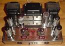
I just noticed that the PCB around my output tube sockets looks like it's been getting hot. The board replacements did not have the socket holes with the notches on the sides for extra airflow and I didn't know how to do it without wrecking them. So when I put my ceramic sockets in they just barley fit so after they warm up could it get the PCB hot enough to cause my intermittent problems? Here is a older pic showing the output sockets I'm talking about but this is when it was new so you wont see any heat effects.
-
K-MAN - Posts: 160
- Joined: Thu Nov 30, 2006 5:12 am
![]() by nyazzip » Fri Nov 07, 2008 12:24 am
by nyazzip » Fri Nov 07, 2008 12:24 am
is the evidence of heat black or white looking, or, more brownish? black/whitish deposits i would think would be indicators of crazy-hot arc temps, whereas brown toasty looking colors would be more of a sub-1000F "baking" type heat.
as far as spacing and holes, virtually all of the output tube heat is created above the PCB surface, and heat rises, so...heat produced by the output tubes should not be much of a factor, IMO, assuming the amp is used as designed, ie in the upright "attitude"...
the ceramic sockets shouldn't conduct much heat back down into the PCB either.
maybe some of those PCB traces are arcing over to something else? those nuts look awfully close to the tube base contacts, but i assume thats a tried and true design.
maybe you should operate the amp upsidedown and apart, so you can look at it when the crackling sound is actually occurring?
just my 2 zimbawean cents
I just noticed that the PCB around my output tube sockets looks like it's been getting hot. The board replacements did not have the socket holes with the notches on the sides for extra airflow and I didn't know how to do it without wrecking them. So when I put my ceramic sockets in they just barley fit so after they warm up could it get the PCB hot enough to cause my intermittent problems? Here is a older pic showing the output sockets I'm talking about but this is when it was new so you wont see any heat effects.
<i>the poor craftsman blames his tools</i>
-

nyazzip - KT88
- Posts: 1073
- Joined: Wed Jan 09, 2008 1:24 am
![]() by EWBrown » Fri Nov 07, 2008 9:28 am
by EWBrown » Fri Nov 07, 2008 9:28 am
With this kind of problem, it is always best to look for the simplest possible causes first:
I have found that most of the Chinese made ceramic 9 pin sockets tend to have fairly tight contacts, so new sockets shouldn't exhibit loose pin issues. The looseness issue can occur if the first tube plugged into ithe socket had "fat" pins" then subsequent tubes (like J/Js) have skinnier pins.
According to the Gurus over at Bottlehead, about 99% of this kind of problems can be traced back to a poor solder connection. This was found when they repair / correct customers' kits which have "issues".
The next level of probability is a misbehaving resistor, sometimes the connection from the lead to the resistor's insies can get comprolised during soldering - this is most true with carbon composition resistors, but it can happen with metal films and wirewounds. too.
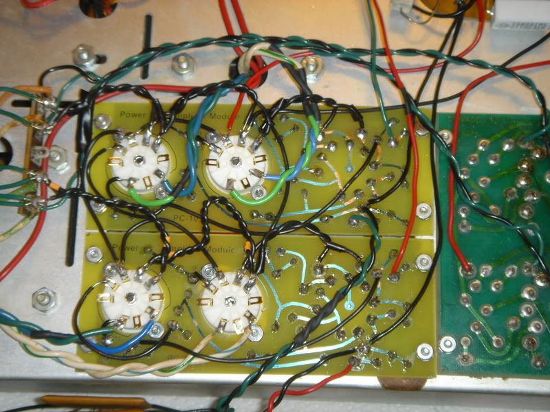
Your solder connections look to be good from the photographs, but I'd take a closer look at the soldering on the filament pins 4 and 5 on the lower right hand side EL84 socket. Also Pin 2 on the lower left side EL84 socket, it looks a tad "sparse".
Even a nice shiny and smooth looking solder flow can hide a weak electrical connection, if the wire itself has any oxidation or corrosion on it.
One good and easy method of tracking down the "culprit" is to tap all the connections gently with an insulated dowel ir wooden / plastic stick (or chopstick). Don't use anything conductive, for this procedure.
When in doubt, re-flow all the connections on the crackly channel's PC board.
The most "browned" area of the PC boards seems to be the space between all four EL84s, and that will be the main "hot spot" for radiated heat from the tubes, and which has the least air flow.
HTH
/ed B
I have found that most of the Chinese made ceramic 9 pin sockets tend to have fairly tight contacts, so new sockets shouldn't exhibit loose pin issues. The looseness issue can occur if the first tube plugged into ithe socket had "fat" pins" then subsequent tubes (like J/Js) have skinnier pins.
According to the Gurus over at Bottlehead, about 99% of this kind of problems can be traced back to a poor solder connection. This was found when they repair / correct customers' kits which have "issues".
The next level of probability is a misbehaving resistor, sometimes the connection from the lead to the resistor's insies can get comprolised during soldering - this is most true with carbon composition resistors, but it can happen with metal films and wirewounds. too.
Your solder connections look to be good from the photographs, but I'd take a closer look at the soldering on the filament pins 4 and 5 on the lower right hand side EL84 socket. Also Pin 2 on the lower left side EL84 socket, it looks a tad "sparse".
Even a nice shiny and smooth looking solder flow can hide a weak electrical connection, if the wire itself has any oxidation or corrosion on it.
One good and easy method of tracking down the "culprit" is to tap all the connections gently with an insulated dowel ir wooden / plastic stick (or chopstick). Don't use anything conductive, for this procedure.
When in doubt, re-flow all the connections on the crackly channel's PC board.
The most "browned" area of the PC boards seems to be the space between all four EL84s, and that will be the main "hot spot" for radiated heat from the tubes, and which has the least air flow.
HTH
/ed B
Real Radios Glow in the Dark
-

EWBrown - Insulator & Iron Magnate
- Posts: 6389
- Joined: Wed Mar 19, 2003 6:03 am
- Location: Now located in Clay County, NC !
8 posts
• Page 1 of 1
Who is online
Users browsing this forum: No registered users and 13 guests