Ok so I have followed the instructions quite well, ordered the parts and installed them. I got a chassis from triode electronics, along with some other items for the finishing touches.
But I have run into a big problem, I can't seem to find any information about wiring this thing up. I used dynaco transformers from a sca35, both power and output. I would be very happy if one of you fine tubeheads could lay it out for me, real easy like. See if you can dynaco up the instructions so anyone can do it. Remember I have no wires attached inside the chassis as this seems to be the point where the instructions stop Yellow_Light_Colorz_PDT_09 . Thanks guys.
DIY st35 Board question
7 posts
• Page 1 of 1
DIY st35 Board question
![]() by vintage » Sat Jul 05, 2008 12:57 pm
by vintage » Sat Jul 05, 2008 12:57 pm
- vintage
- Posts: 10
- Joined: Sun Jun 29, 2008 9:02 am
![]() by Ty_Bower » Sat Jul 05, 2008 1:39 pm
by Ty_Bower » Sat Jul 05, 2008 1:39 pm
The wiring layout should be on page 14 of the manual:
http://www.diytube.com/phpBB2/viewtopic.php?t=837
Tom has a good photo of the wiring at the top of his page, too.
http://tmamps.com/
http://www.diytube.com/phpBB2/viewtopic.php?t=837
Tom has a good photo of the wiring at the top of his page, too.
http://tmamps.com/
-

Ty_Bower - KT88
- Posts: 1494
- Joined: Wed Mar 21, 2007 2:50 pm
- Location: Newark, DE
![]() by Shannon Parks » Sun Jul 06, 2008 6:04 am
by Shannon Parks » Sun Jul 06, 2008 6:04 am
The secondary center for the cloth leaded PA774 will basically look yellow or dull brown, instead of red/yellow. I think there was a little bit of red in there forty years ago. 
- designer of fine tube audio gear at (((parks audio)))
- founder and admin of the diytube forums
-

Shannon Parks - Site Admin
- Posts: 3764
- Joined: Tue Mar 18, 2003 5:40 pm
- Location: Poulsbo, Washington
![]() by Ty_Bower » Sun Jul 06, 2008 6:45 am
by Ty_Bower » Sun Jul 06, 2008 6:45 am
I missed the part where you said they were Dynaco originals. I assumed they were new reproductions from Triode.
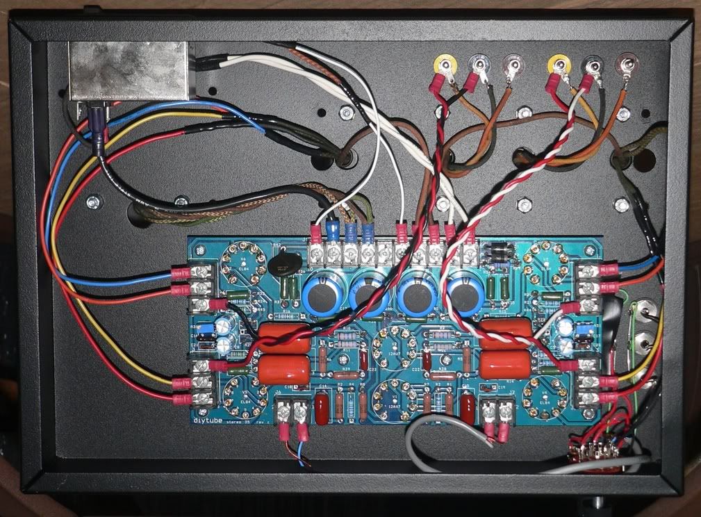
Here's a DIY ST35 chassis I assembled using original Dynaco transformers. Unfortunately, many of the leads were too short and I had to add extensions. The colors I used were somewhat random, so follow them carefully.
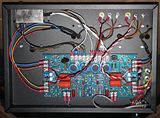
Here's a DIY ST35 chassis I assembled using original Dynaco transformers. Unfortunately, many of the leads were too short and I had to add extensions. The colors I used were somewhat random, so follow them carefully.
-
Ty_Bower - KT88
- Posts: 1494
- Joined: Wed Mar 21, 2007 2:50 pm
- Location: Newark, DE
7 posts
• Page 1 of 1
Who is online
Users browsing this forum: No registered users and 2 guests