I'm sure this has been discussed a ton of times, but I might have a SCA-35 coming my way in the next few weeks. I'm wondering what to do to it. Obviously, I'll bypass the tone controls, and at the very least, replace all caps and probably add a choke to the PSU.
I don't really like the asymmetrical look of the SCA-35, and would probably rather rebuild it as a straight up power amp into a new aluminum chassis, but if I go that route, where does it stop? The "ultimate" use for the Dynaco iron would probably be choke input and fixed bias, using the same adjustment scheme as in the Eiclone. 330V should give a very stiff 300V, not even factoring in higher line voltage. At 40mA/tube, that's a nice healthy 12W per EL84. What do you think? I'd probably use a Hammond 193M (10H 63R .3A) for the job.
I still haven't decided on a tube topology for the amp but was thinking along the lines of Poindexter's implementation of a 5965, which would work nicely with the whole fixed-bias idea anyway by using one of those small Amveco toroids...
I assume that resale value shouldn't be too bad in either case, on the one hand for authenticity, on the other for pure sound quality...
SCA-35
36 posts
• Page 1 of 3 • 1, 2, 3
![]() by TomMcNally » Sat Nov 24, 2007 8:04 pm
by TomMcNally » Sat Nov 24, 2007 8:04 pm
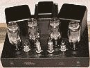
I have an SCA-35 in unusually nice condition.
All I did was replace the coupling caps in the amp,
and put new tubes in it. It sounds great.
I vote for authenticity ! Why destroy an antique
to grab a few transformers.
All I did was replace the coupling caps in the amp,
and put new tubes in it. It sounds great.
I vote for authenticity ! Why destroy an antique
to grab a few transformers.
-

TomMcNally - Darling du Jour
- Posts: 2729
- Joined: Sat Nov 19, 2005 2:19 pm
- Location: Northfield, NJ
![]() by CpuZapper » Sat Nov 24, 2007 10:44 pm
by CpuZapper » Sat Nov 24, 2007 10:44 pm
I have been messing with a SCA-35, for me the stock sound was not very good. The best way I can describe it is unfocused, if I tried to focus on a single instrument it was very hard to follow.
I removed the controls and replaced the volume pot, this helped clean up the sound a little along with more detail. I also played with a voltage divider to get as much gain without causing trouble with the volume pot's natural progression.
But the biggest improvement "FOR ME" was replacing the 7199's with Tungsram 6U8A's. The sound is now much more focused and musical to listen to. I made adapters to use the 6U8A tubes so it can be reversed in seconds, if needed.
I seem to enjoy the sound of Tungsram tubes where ever I have tried them and the 6U8A's were less than a dollar each (Off Ebay) so not much of a waste if you don't like them.
Let us know what you think of the SCA-35 sound when you get it.
-
CpuZapper - Posts: 116
- Joined: Tue Jul 03, 2007 7:35 pm
- Location: Alberta, Canada
![]() by TomMcNally » Sat Nov 24, 2007 10:58 pm
by TomMcNally » Sat Nov 24, 2007 10:58 pm
Yeah slide a choke in there !
Those SCA-35's do run pretty hot though ...
a fan on top might not be a bad thing.

Those SCA-35's do run pretty hot though ...
a fan on top might not be a bad thing.
-
TomMcNally - Darling du Jour
- Posts: 2729
- Joined: Sat Nov 19, 2005 2:19 pm
- Location: Northfield, NJ
![]() by sorenj07 » Sat Nov 24, 2007 11:13 pm
by sorenj07 » Sat Nov 24, 2007 11:13 pm
all right, cool. I'm also considering the idea of replacing the one-size-fits-all cathode bias resistor for the output tubes with four separate ones, which should be a bit more forgiving of unmatched tubes. I might even install some bias adjustment pots in there as well. I've never worked with one of these though so I'll have to take a look under the hood and see exactly how much room I have to monkey around...
one question: what is the standard operating point for the output tubes in this amp? plate voltage, plate to cathode voltage, bias voltage, current, etc.?
one question: what is the standard operating point for the output tubes in this amp? plate voltage, plate to cathode voltage, bias voltage, current, etc.?
-
sorenj07 - KT88
- Posts: 925
- Joined: Tue May 02, 2006 2:39 pm
- Location: Berlin
![]() by Shannon Parks » Sun Nov 25, 2007 7:08 am
by Shannon Parks » Sun Nov 25, 2007 7:08 am
SCA35 Tips
1) You might skip the tone controls mod. I did it and added a lot of hum.
2) Throw a muffin fan on top!
3) Look for all the circuit mods added over the years. :)
1) You might skip the tone controls mod. I did it and added a lot of hum.
2) Throw a muffin fan on top!
3) Look for all the circuit mods added over the years. :)
- designer of fine tube audio gear at (((parks audio)))
- founder and admin of the diytube forums
-

Shannon Parks - Site Admin
- Posts: 3764
- Joined: Tue Mar 18, 2003 5:40 pm
- Location: Poulsbo, Washington
![]() by joeriz » Sun Nov 25, 2007 7:35 am
by joeriz » Sun Nov 25, 2007 7:35 am
While we're on the subject of the SCA-35...
Is there anything 'wrong' with simply removing the 12AX7s in the phono stage? I assume voltages to the other tubes may rise slightly. On the flip side, I suppose there would also be slightly less strain on the power transformer. My otherwise perfectly-working unit develops a quiet-but-noticable high-pitched ringing after about ten minutes of warm up that I've traced to the phono board. This eventually stops after about another 10-15 minutes but it's annoying. I use this amp in my bedroom system and never use the phono stage so I'm in no hurry to try to fix it.
Thanks,
Joe
- joeriz
- Posts: 102
- Joined: Thu Jun 01, 2006 12:34 pm
![]() by Ty_Bower » Sun Nov 25, 2007 8:51 am
by Ty_Bower » Sun Nov 25, 2007 8:51 am
The voltages might rise more than you'd expect. I pulled a pair of 12AU7 and a 12AX7 from the phono stage of a HK A230 amp. The 215 volt rail jumped up to 265 volts. I didn't know if this was a problem or not, so I rigged a dummy load out of a 30k ohm, 5 watt cemented resistor. It brought the voltages back into line.
-

Ty_Bower - KT88
- Posts: 1494
- Joined: Wed Mar 21, 2007 2:50 pm
- Location: Newark, DE
![]() by TomMcNally » Sun Nov 25, 2007 9:42 am
by TomMcNally » Sun Nov 25, 2007 9:42 am
Soren -
I'm sure you found this - but here is a link to the original manual.
It has a complete voltage chart.
http://www.curcioaudio.com/SCA35%20Manual.pdf
I'm sure you found this - but here is a link to the original manual.
It has a complete voltage chart.
http://www.curcioaudio.com/SCA35%20Manual.pdf
-
TomMcNally - Darling du Jour
- Posts: 2729
- Joined: Sat Nov 19, 2005 2:19 pm
- Location: Northfield, NJ
![]() by TerrySmith » Sun Nov 25, 2007 10:10 am
by TerrySmith » Sun Nov 25, 2007 10:10 am
Yes, pull the 12AX7's if not using a turntable. Also remove the pilot lamp and replace with a LED, fits the hole perfectly.
Seperate cathode resistors is the only way to go on the SCA-35, (and Heathkit AA-151's too), I've been using 430 - 470 ohm resistors and 470uf caps.
Seperate cathode resistors is the only way to go on the SCA-35, (and Heathkit AA-151's too), I've been using 430 - 470 ohm resistors and 470uf caps.
T. Smith
-

TerrySmith - KT88
- Posts: 973
- Joined: Sat Jan 31, 2004 12:51 pm
- Location: Maryville TN
![]() by EWBrown » Tue Dec 04, 2007 6:44 am
by EWBrown » Tue Dec 04, 2007 6:44 am
Depending on your local AC line voltage, the B+ at the OPT Center taps in the SCA-35 can vary between 365 to 380VDC. Estimate a 6V IR drop through the OPT primary, and approx 14 - 15V through the individual cathode resistors (390 to 430 ohms @ 35 mA). So we're looking at between 344 to 360V Plate to cathode for each EL84, which is within its plate dissipation ratings.
I'd suggest inserting a CL-90 Inrush Current Limiter in the primary AC side of the power trannie, in any SCA-35 or ST-35 rebuilds, this will eliminate that hard power-on "slam" and reduce the B+ voltages slightly, by a matter of just a few volts. THis is even more important with the increased capacitance in the PSU.
The signal path wiring behind the front panel is a veritable Minotaur's Maze of unshielded wiring and PECs, ceramic caps and other things that go bump in teh night whilst tormenting the sound quality, and picking up every stray EM signal in the area... I'd ditch the tone controls, filters, and perhaps keep the original volume and balance pots, if they are in good condition. If the phono or tape head stage isn't required, just ditch it and stick with the basic power amp section.
In my first SCA-35 redemption of a "ridden hard and put-up wet" carcass, found on E-bay before the prices went up on these, I ended up using only the original iron, and chassis, and replaced the crispy toasted SCA35 PCBs with aftermarket ST-35 boards (using 7247 / 12DW7) and beefed up the power supply to be more or less equal to that on the DIY35 boards.
The preamp board and selector swith was also excised, and I made up a plate to carry the extra electrolytic caps, and mounted a C354 choke on top of the chassis, close to the original preamp board's location. Circuit topology is more or less identical to that on the DIY-35's PSU section.
I started out with the original volume and balance controls, but later replaced them with one of the Hong Kong 100K stereo stepped attenuators. The original controls were just a tad scratchy and intermittent, and a few attempts at using TV tuner cleaner only gave temporary results.
I didn't bother with multiple input selectors, and added a separate pair of isolated RCA jacks on the back panel (someone had previously very conveniently drilled two 3/8 in diameter holes in just the right location), and ran shielded cable from those to the step attenuator and more shielded wire to the inputs of the PRCs. The unit still has the original phenolic speaker terminals, I may eventually replace those with binding posts, as I typically only use the 8 ohm outputs.
I filled the now-empty holes in the front panel with some Dialco LED pilot lamps, one gives a power-on indication, another samples the DC voltage across the shared cathode resistor in order to show thatit is fully warmed up. (I still have to replace that with individual 390 -430 ohm resistors and 330 uF 35V caps, and then each cathode can have an LED "monitor").
The other SCA-35 I have from a flea market find, was factory built and in such pristine condition that I left it intact.
HTH
/ed B in NH
Real Radios Glow in the Dark
-

EWBrown - Insulator & Iron Magnate
- Posts: 6389
- Joined: Wed Mar 19, 2003 6:03 am
- Location: Now located in Clay County, NC !
![]() by K-MAN » Tue Dec 04, 2007 4:06 pm
by K-MAN » Tue Dec 04, 2007 4:06 pm
The SCA35 is pretty good the way it is I think, I've kept mine original except for replacing the crispy pc boards with new reproduction's and it's perfect for listening to either my turntable or mp3's from my computer. The mods like taking out the tone controls might help but I think it takes away allot of the collector value from them if you ever go to resell it, Ebay is full of ones that have had all sorts of things done to them that seem to take away from the vintage charm of Dynaco's.
-

K-MAN - Posts: 160
- Joined: Thu Nov 30, 2006 5:12 am
![]() by Slartibartfast » Tue Dec 04, 2007 5:52 pm
by Slartibartfast » Tue Dec 04, 2007 5:52 pm
K-MAN wrote:The SCA35 is pretty good the way it is I think, I've kept mine original except for replacing the crispy pc boards with new reproduction's and it's perfect for listening to either my turntable or mp3's from my computer. The mods like taking out the tone controls might help but I think it takes away allot of the collector value from them if you ever go to resell it, Ebay is full of ones that have had all sorts of things done to them that seem to take away from the vintage charm of Dynaco's.
All this favorable talk of the SCA35 has got me perusing the ebay ads. This would be good to power my system in the den, so I could use my ST70 to drive the Klipsch LaScalas I recently acquired.
-

Slartibartfast - KT88
- Posts: 458
- Joined: Sun Apr 15, 2007 9:40 pm
- Location: Columbia S.C.
36 posts
• Page 1 of 3 • 1, 2, 3
Who is online
Users browsing this forum: No registered users and 9 guests