1773C

for the DIY ST35, the Dynakit and every other PP EL84

1773C

Postby erichayes » Wed Oct 17, 2007 6:00 pm

Image


This is a test to see if I have Photobucket somewhat mastered. Thanks Ty.

This is a "conceptual prototype" of a 1773 on a polished 304 stainless chassis. It never got wired--we just wanted to get people's reaction. The transformer bells are 95% black instead of the 50% we used for the regular bells.

The chassis is now residing with Bud in Warren OH and the iron has been absorbed into the system.
Eric in the Jefferson State
erichayes
KT88
 
Posts: 987
Joined: Fri Jan 23, 2004 9:01 pm
Location: McKinleyville CA

Postby Ty_Bower » Wed Oct 17, 2007 6:31 pm

Looks good to me. :) I've read multiple references to the 1773, but I don't think I've ever seen a photo. I always wondered what it looked like...
User avatar
Ty_Bower
KT88
 
Posts: 1494
Joined: Wed Mar 21, 2007 2:50 pm
Location: Newark, DE

Postby TomMcNally » Wed Oct 17, 2007 7:50 pm

Very cool chassis.

Maybe you could let us see some more of your work
when you have some time Eric.
I googled you and didn't find a web page or anything.

... tom
User avatar
TomMcNally
Darling du Jour
 
Posts: 2729
Joined: Sat Nov 19, 2005 2:19 pm
Location: Northfield, NJ

Postby Ty_Bower » Fri Apr 25, 2008 8:48 pm

I don't want to ask you to give away all your secrets, but...

The output tubes are 6BQ5 (EL84/6p14p), of course. The splitters look like 12BH7 long tailed pairs? But what is the driver tube hiding under the RF shield?
User avatar
Ty_Bower
KT88
 
Posts: 1494
Joined: Wed Mar 21, 2007 2:50 pm
Location: Newark, DE

Postby sorenj07 » Fri Apr 25, 2008 10:40 pm

Looks pretty cool except it's "backwards" - I always put my PSU on the left, and my output tubes on the right for some reason! Other than that, it looks cool. Wouldn't mind seeing a nice big choke on top, and the RCA jacks in the back, but hey. Good work :)
User avatar
sorenj07
KT88
 
Posts: 925
Joined: Tue May 02, 2006 2:39 pm
Location: Berlin

Postby erichayes » Sat Apr 26, 2008 2:48 pm

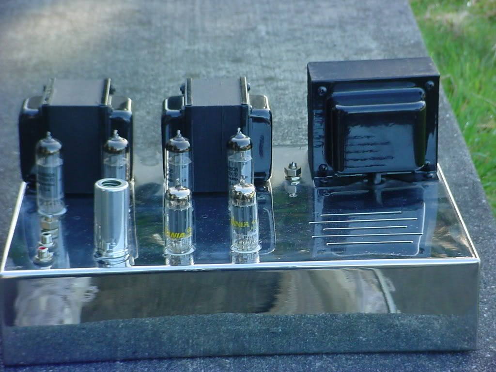
The outputs are, indeed, EL84s--Sovtek non-military, to be exact. The PIs are 6GU7s, one per channel. The shielded tube is a 5751 first audio stage, one section per channel, directly coupled to the grids of the 6GU7s. The circuit is very similar to Shannon's Eiclone or the Eico HF87/89, just tweaked for operating at lower B+ voltages.

I'm in the process of wearing down my commercial photographer daughter to shoot some of the other stuff, but she hasn't quite relented yet. Soon, though.

The power supply is where it is to get it as far away from the input stage as possible (The choke and filter caps are under the chassis to raise the female acceptance factor). Likewise, the input jacks are mounted as close to the input tube as possible. These two ploys bought me an extra 20dB of noise floor. Measured hum and noise is -120dB referenced to 1 watt.
Eric in the Jefferson State
erichayes
KT88
 
Posts: 987
Joined: Fri Jan 23, 2004 9:01 pm
Location: McKinleyville CA

Postby sorenj07 » Sun Apr 27, 2008 12:14 am

Them's are some pretty ridiculous numbers. If you weren't in Cally I'd want to give it a listen. How are you feeding the 6GU7's by the way, is it a CCS or a more traditional negative voltage fed tail?
User avatar
sorenj07
KT88
 
Posts: 925
Joined: Tue May 02, 2006 2:39 pm
Location: Berlin


Return to stereo 35

Who is online

Users browsing this forum: No registered users and 41 guests