Hi,
I am going to take this statement literally:
"for the DIY ST35, the Dynakit and every other PP EL84"
I bought the KN747 OPTs mentioned in this thread:
http://www.diytube.com/phpBB2/viewtopic.php?t=1612
for the purpose of repairing a Kenwood KW-70 EL84 PP receiver with
mismatched OPTs.
The donors were originally mounted in the KN747 with one end bell thru the chassis so that the laminations were parallel to the chassis top. All 8 leads come out of a hole in the center of this bell.
The KW-70 has the transformers mounted with the laminations perpendicular to the chassis and oriented front to back. This transformer has 7 leads, 4 coming out the bottom of one end bell
and 3 out the other. The leads get to the underside of the chassis thru a holes directly below each end bell. The laminations are covered with
a "strap" with a screw hole in each foot for attachment.
Now some questions:
1. Can I mount the donor KN747 OPTs with the laminations parallel to the chassis top? This would result in the PT & OPTs all having the laminations parallel to the chassis top. This is the same configuration of my Heathkit AA-151.
2.Can I mount them on a bracket above the chassis?( There is too much under the chassis to cut a hole).
3. The laminations in the AA-151 are not square and they are all mounted long dimension fro and aft. I propose to mount the donors the same way.
Is this acceptable?
4. If above are doable, could I drill two more holes in the end bell
on perpendicular faces and route the wires right and left to the holes in the chassis.
My concern here is that the chassis may be RF shielding the wires.
5. I do not have a schematic for the KW-70 (I've searched for 2 years)
so I can not compare it to the KN734 which Eric Hayes will be sending me. Could the KN734's 8th wire be an ultra linear tap?
Thank you for your patience and help,
Vince
PS:I do have, and looked into, Morgan Jone's "Valve Amplifiers".
What I'm really waiting for is someone to write a "Haynes" type
manual!!!
OPT Replacement and Orientation
4 posts
• Page 1 of 1
OPT Replacement and Orientation
![]() by Vince » Mon Jul 23, 2007 3:33 pm
by Vince » Mon Jul 23, 2007 3:33 pm
- Vince
- Posts: 118
- Joined: Thu May 24, 2007 11:34 am
- Location: SF Bay Area
![]() by erichayes » Mon Jul 23, 2007 4:23 pm
by erichayes » Mon Jul 23, 2007 4:23 pm
The best orientation for the OTs is Kenwood's. This has the magnetic force lines running parallel so they don't overlap and cause crosstalk. You didn't say how the PT is mounted, but its laminations should oriented at a right angle to those of the OTs.
An "F" style transformer can be mounted in an upright position, although you might have to extend the leads. You can either buy or fabricate L brackets and mount them using the bolts holding the bells on, or look for some junk transformers and harvest the bells from them to put on the Knights. If you have a decent drill press and vise, you should be able to poke holes in the bells; just make sure they're clean with no burrs.
The 8th lead is the 32Ω secondary lead, colored green/yellow, and can be taped and ignored.
Eric in the Jefferson State
- erichayes
- KT88
- Posts: 987
- Joined: Fri Jan 23, 2004 9:01 pm
- Location: McKinleyville CA
![]() by Ty_Bower » Mon Jul 23, 2007 6:52 pm
by Ty_Bower » Mon Jul 23, 2007 6:52 pm
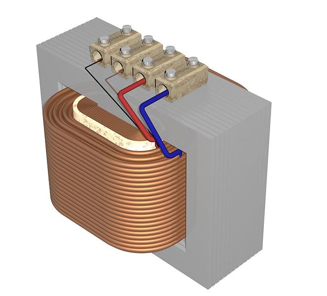
I spent a lot of time trying to understand the direction of the lines of magnetic flux. Here's a nice picture of a transformer similar to our power and output transformers (credit goes to Wikipedia):

Here's another nice picture I found of a 20:1 "transformer". The primary winding has leads to the left, and the secondary has leads to the right. The primary has twenty turns; the secondary has but one. The secondary is wound right around the primary. The transformer iron is not shown in the picture.

The lines of flux can be seen radiating from the center of the winding, out the top, around the outside of the winding, and back into the bottom center. Really, the flux lines completely encircle the coil, forming a torus. It's tough to find a good drawing that represents this well. The iron of the transformer is there to help "guide" the flux. Ideally, the iron would completely encircle the winding, but this is not possible - how would the transformer be wound?
Coupling occurs between two adjacent transformers when the lines of flux from one transformer escape the iron. These flux lines may "cut" another winding, resulting in a current flow (in our case, causing 60 Hz hum in the outputs).
The usual advice is to align the transformers so the laminations are perpendicular to each other. I'm not sure this always works. Imagine three transformers, arranged in space before you from left to right. The core of each transformer is aligned vertically, pointing up and down. The laminations are all lying flat in the same plane. I think most would agree this is not an ideal arrangement. Now, if the center transformer were to be turned about its core. The core still points up and down, but the laminations are now "popping" out of the page, and extending beneath it. Yes, I realize my description is useless without pictures. Technically, the laminations are perpendicular to each other, but the cores are still all pointing the same direction. I'd imagine that any flux that escaped the iron and followed its usual torus shaped path might happen to intersect the nearby coil of the adjacent transformer.
Of course, I'm not an expert on transformers. I'm probably wrong on many counts. But, it seems to me the best alignment might be to make sure the cores are never parallel to each other - don't just look at the laminations.
Here's another nice picture I found of a 20:1 "transformer". The primary winding has leads to the left, and the secondary has leads to the right. The primary has twenty turns; the secondary has but one. The secondary is wound right around the primary. The transformer iron is not shown in the picture.
The lines of flux can be seen radiating from the center of the winding, out the top, around the outside of the winding, and back into the bottom center. Really, the flux lines completely encircle the coil, forming a torus. It's tough to find a good drawing that represents this well. The iron of the transformer is there to help "guide" the flux. Ideally, the iron would completely encircle the winding, but this is not possible - how would the transformer be wound?
Coupling occurs between two adjacent transformers when the lines of flux from one transformer escape the iron. These flux lines may "cut" another winding, resulting in a current flow (in our case, causing 60 Hz hum in the outputs).
The usual advice is to align the transformers so the laminations are perpendicular to each other. I'm not sure this always works. Imagine three transformers, arranged in space before you from left to right. The core of each transformer is aligned vertically, pointing up and down. The laminations are all lying flat in the same plane. I think most would agree this is not an ideal arrangement. Now, if the center transformer were to be turned about its core. The core still points up and down, but the laminations are now "popping" out of the page, and extending beneath it. Yes, I realize my description is useless without pictures. Technically, the laminations are perpendicular to each other, but the cores are still all pointing the same direction. I'd imagine that any flux that escaped the iron and followed its usual torus shaped path might happen to intersect the nearby coil of the adjacent transformer.
Of course, I'm not an expert on transformers. I'm probably wrong on many counts. But, it seems to me the best alignment might be to make sure the cores are never parallel to each other - don't just look at the laminations.
-

Ty_Bower - KT88
- Posts: 1494
- Joined: Wed Mar 21, 2007 2:50 pm
- Location: Newark, DE
![]() by Vince » Tue Jul 24, 2007 6:14 pm
by Vince » Tue Jul 24, 2007 6:14 pm
Hi Eric and Ty,
The power transformer is mounted with the laminations parallel to the chassis top. The axis of the windings is left to right.
I dissembled the OPTs to see how they are wound. Heeding your advice,
I will mount the OPTs with their laminations perpendicular to the chassis top and pointed front to back. The axis of the windings
will be perpendicular to the chassis top.
Now something oddball. While lurking on tube forums over the last couple of years, I came across this statement: that while the OPT's may look like they are mounted the same, they are actually different.
In taking these apart, I confirmed this. These transformers have 3 wires exiting the coil an one side and 5 on the others. They were mounted so that the 5 wire side,for example, was on the right with one transformer
and on the left with the other so they were rotated 180 degrees.
I will need to extend the wires and run them above the chassis for aways. Could this be a source of problems? I have some teflon insulated wire will that be adequate?
Thanks again for your help,
Vince
- Vince
- Posts: 118
- Joined: Thu May 24, 2007 11:34 am
- Location: SF Bay Area
4 posts
• Page 1 of 1
Who is online
Users browsing this forum: Google [Bot] and 37 guests