First chassis - a photo journal

for the DIY ST35, the Dynakit and every other PP EL84

First chassis - a photo journal

Postby Ty_Bower » Sun Jul 01, 2007 4:08 pm

So, I have a piece of aluminum plate. It's cut to about 13" square. The output transformers are Hammond 1620. The power transformer is a mystery part, supposedly from an old Allied amp. You can read more about my PT here:
http://www.diytube.com/phpBB2/viewtopic.php?t=1612

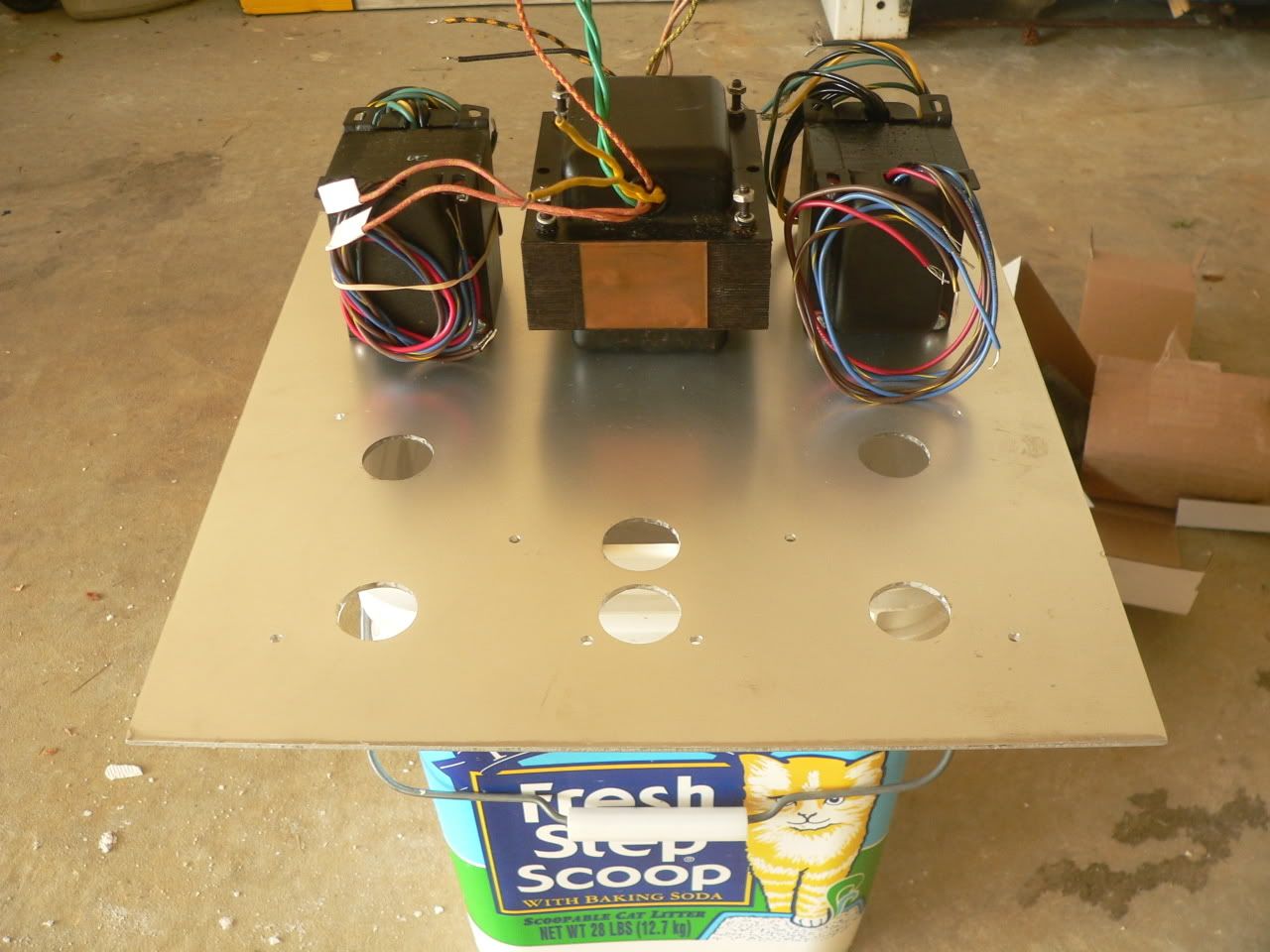
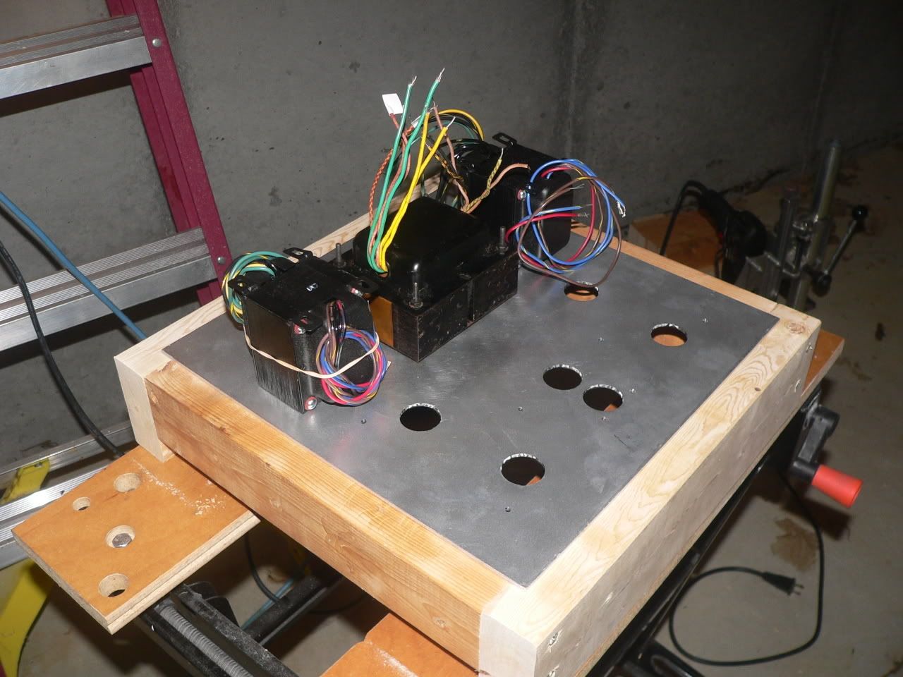
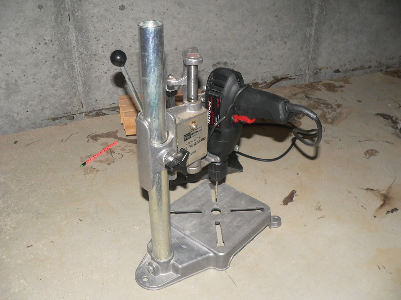
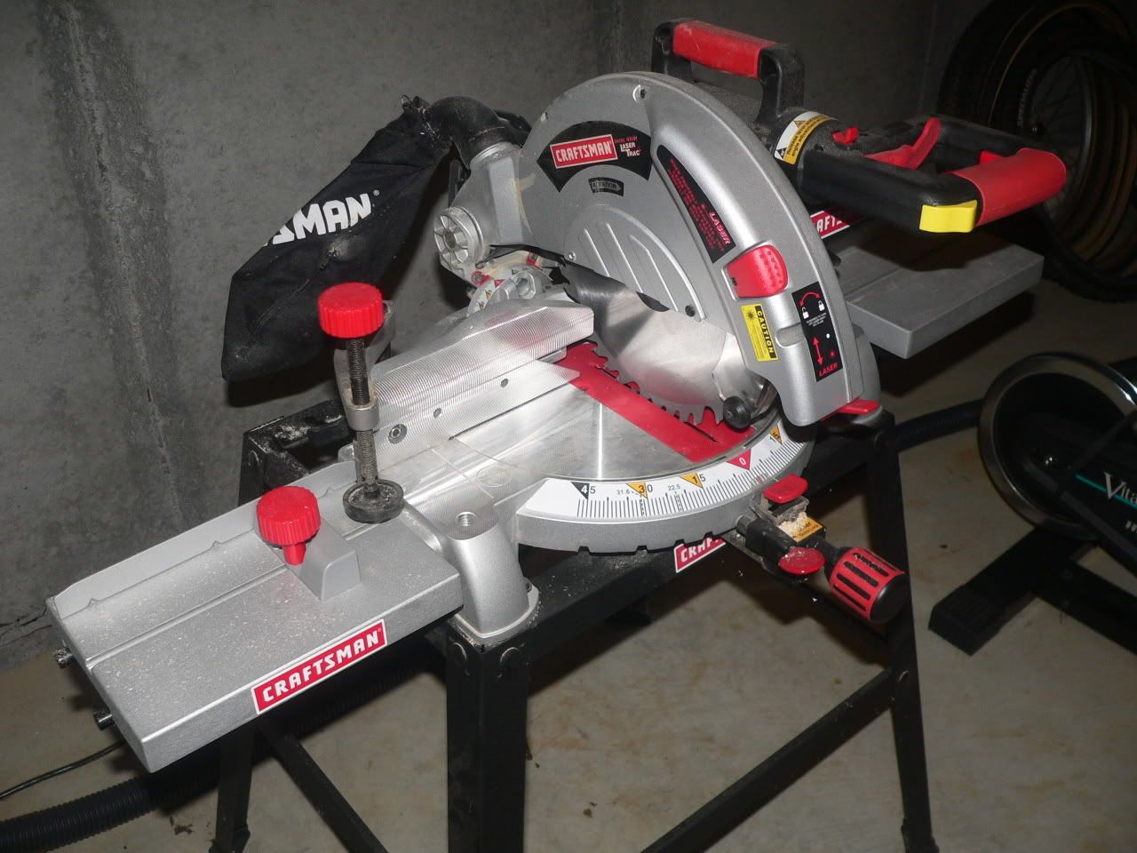
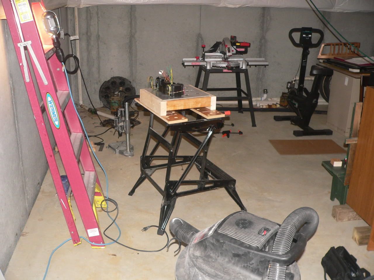
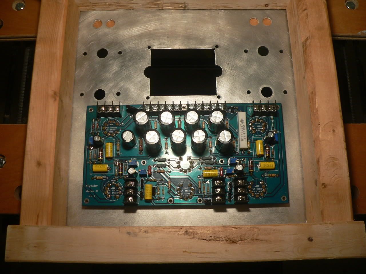
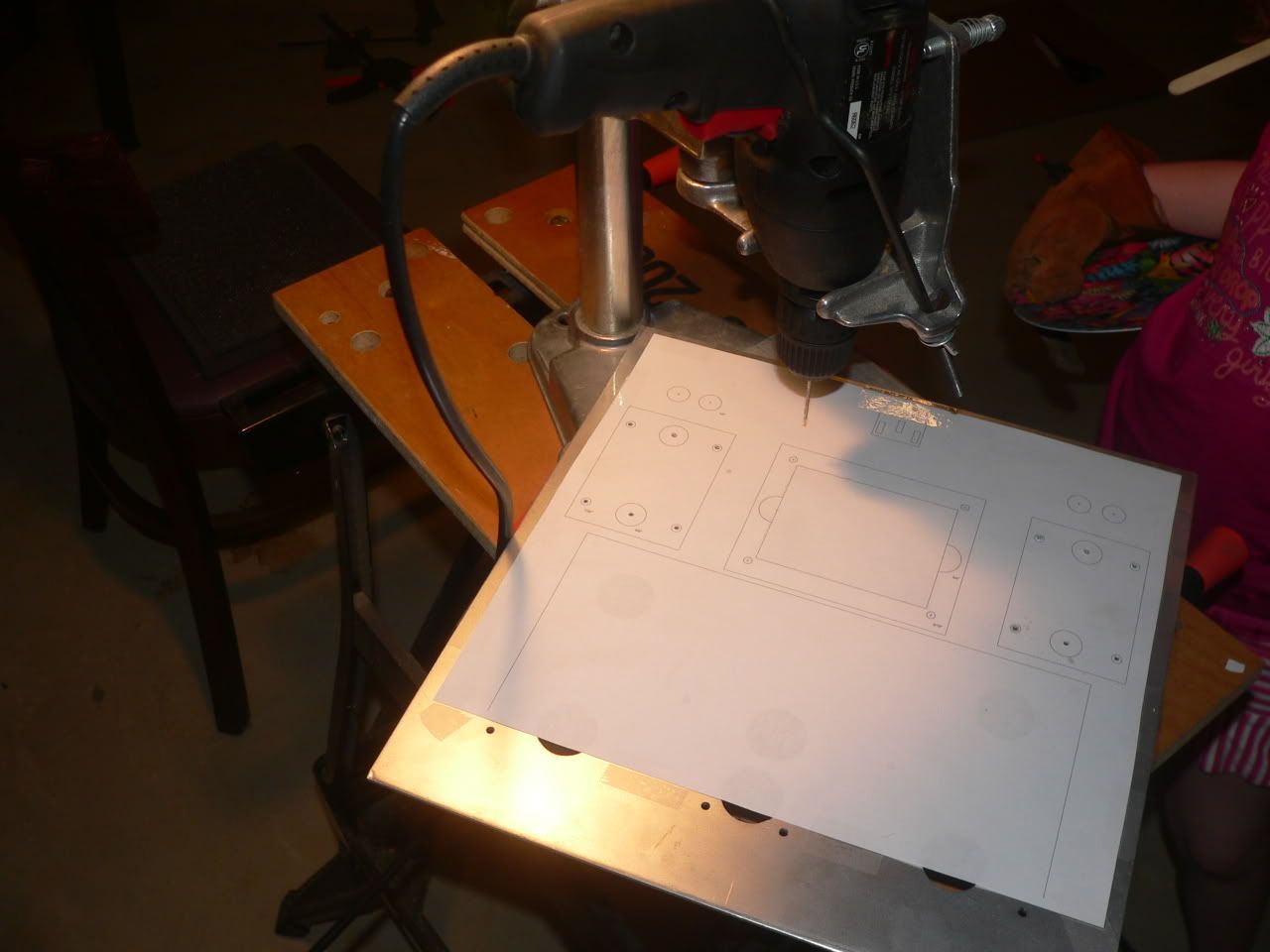
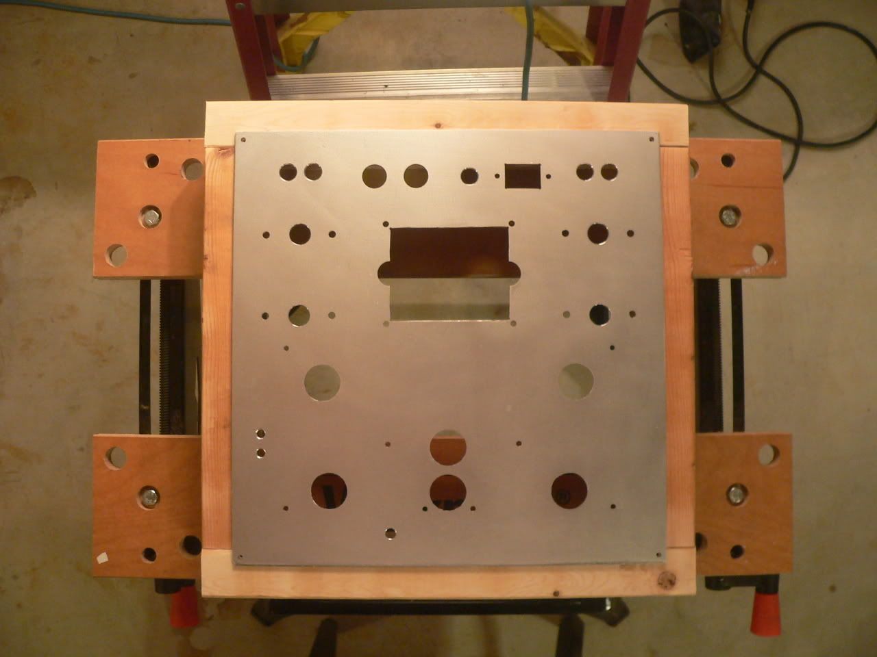
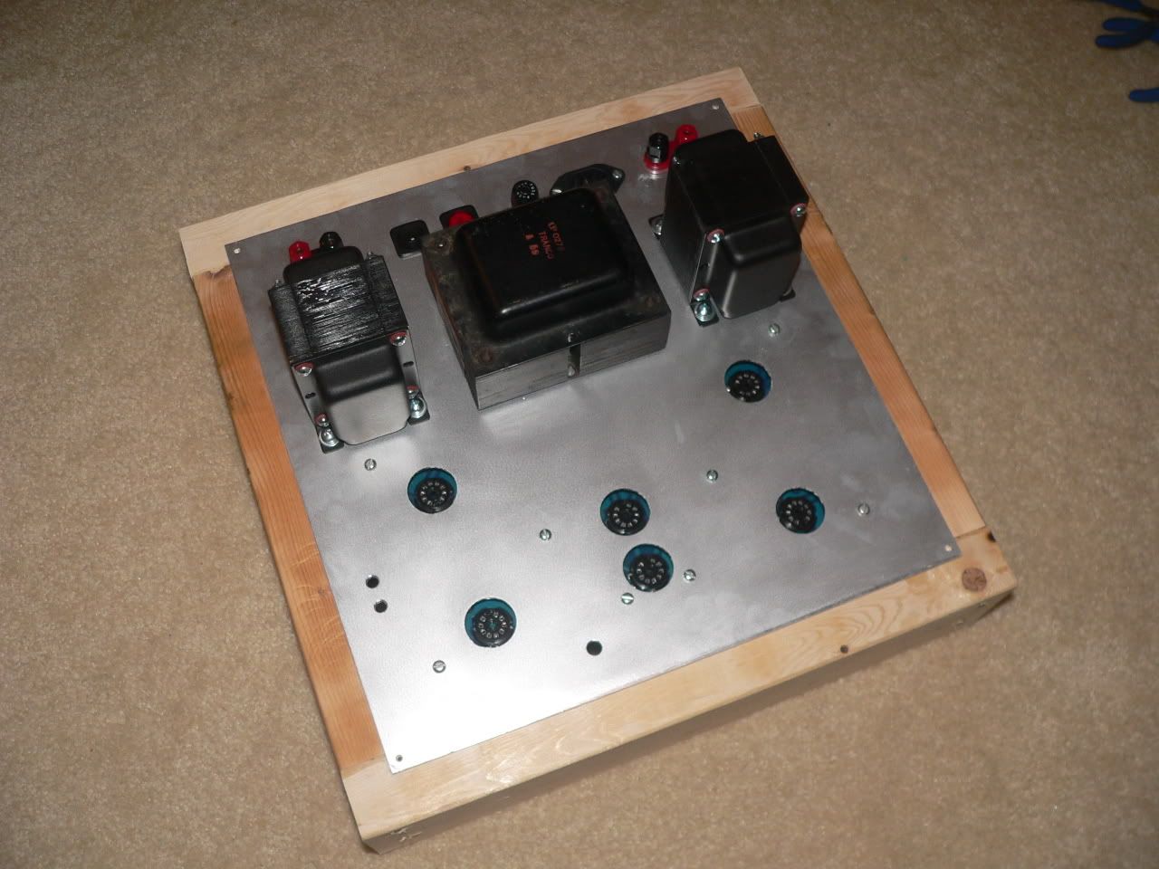
The DIY board is a ST-35, Rev. B. It's already assembled (thanks, Don!). I've drilled the aluminum plate and cut the holes for the tubes. I have essentially no experience with metal work. This took me about four hours just to get this far. The plate started out as an L shaped scrap. I cut the straight lines with a 10" power mitre saw. I still have another rectangular piece left over, about 14" x 9". The holes were all drilled with a hand drill mounted in a stand. I first drilled at all locations with a 5/32" bit. Then I expanded the six tube holes with a 3/4" unibit ($10, Harbor Freight). Finally, a $20 punch set (also Harbor Freight) finished the tube holes. Honestly, the unibit makes a much nicer hole than the cheap punch set. Next time I'd save the money I spent on the punch, and use it to buy a bigger unibit.

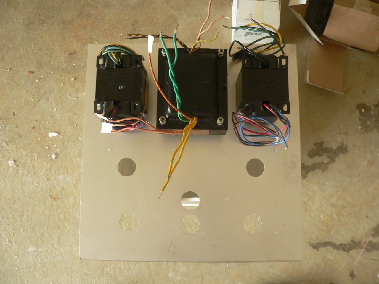
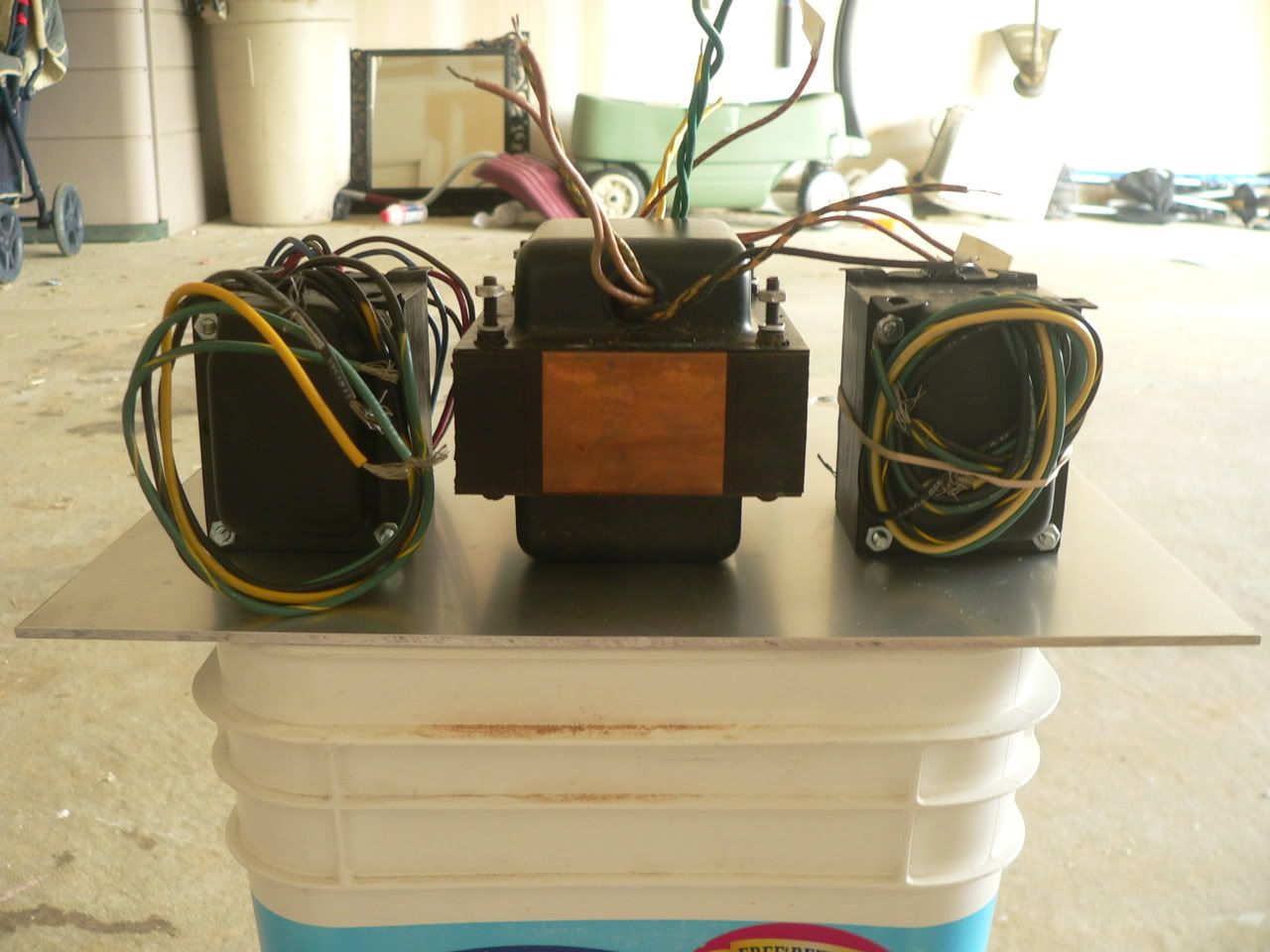
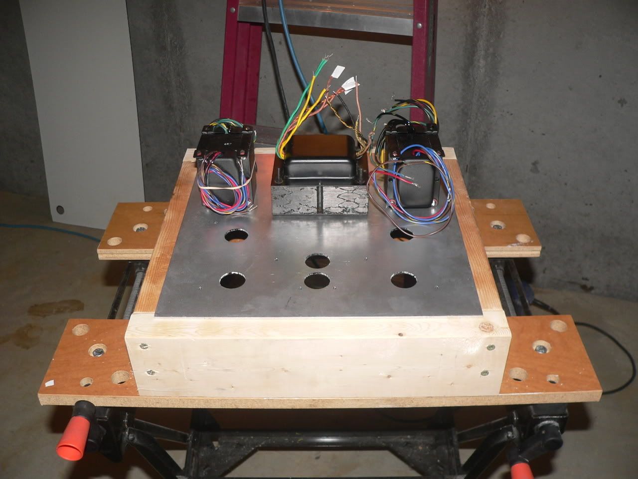
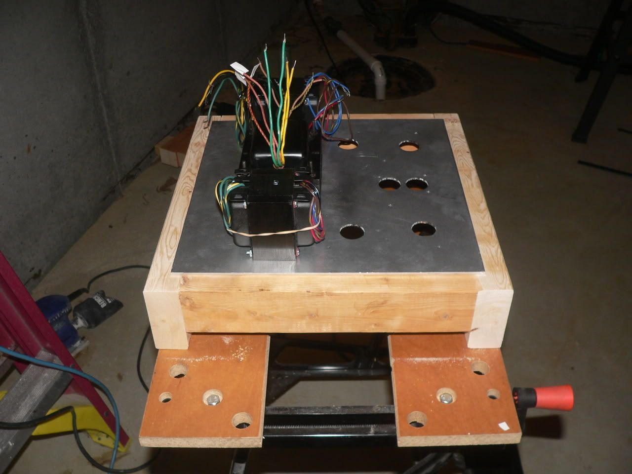
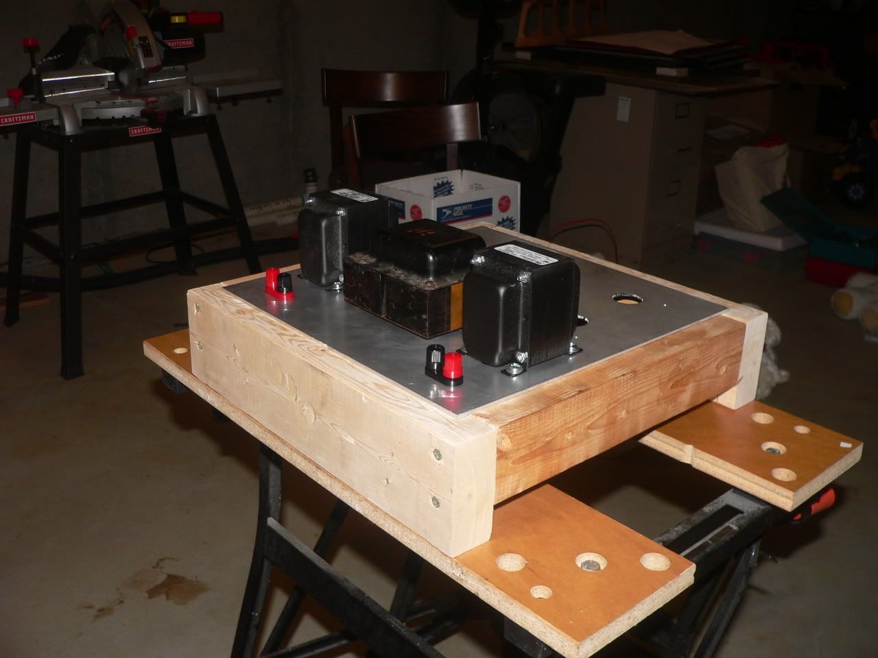
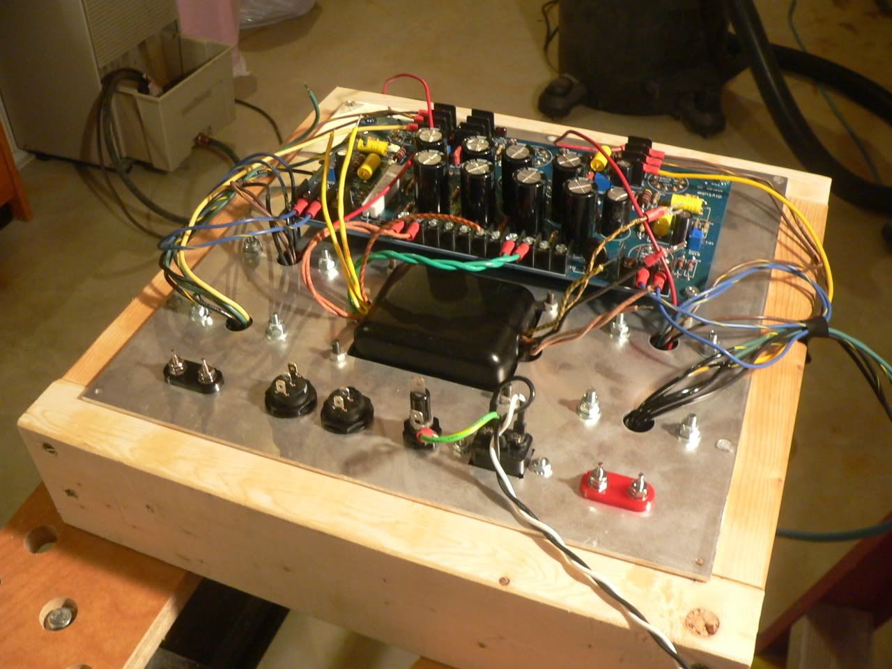
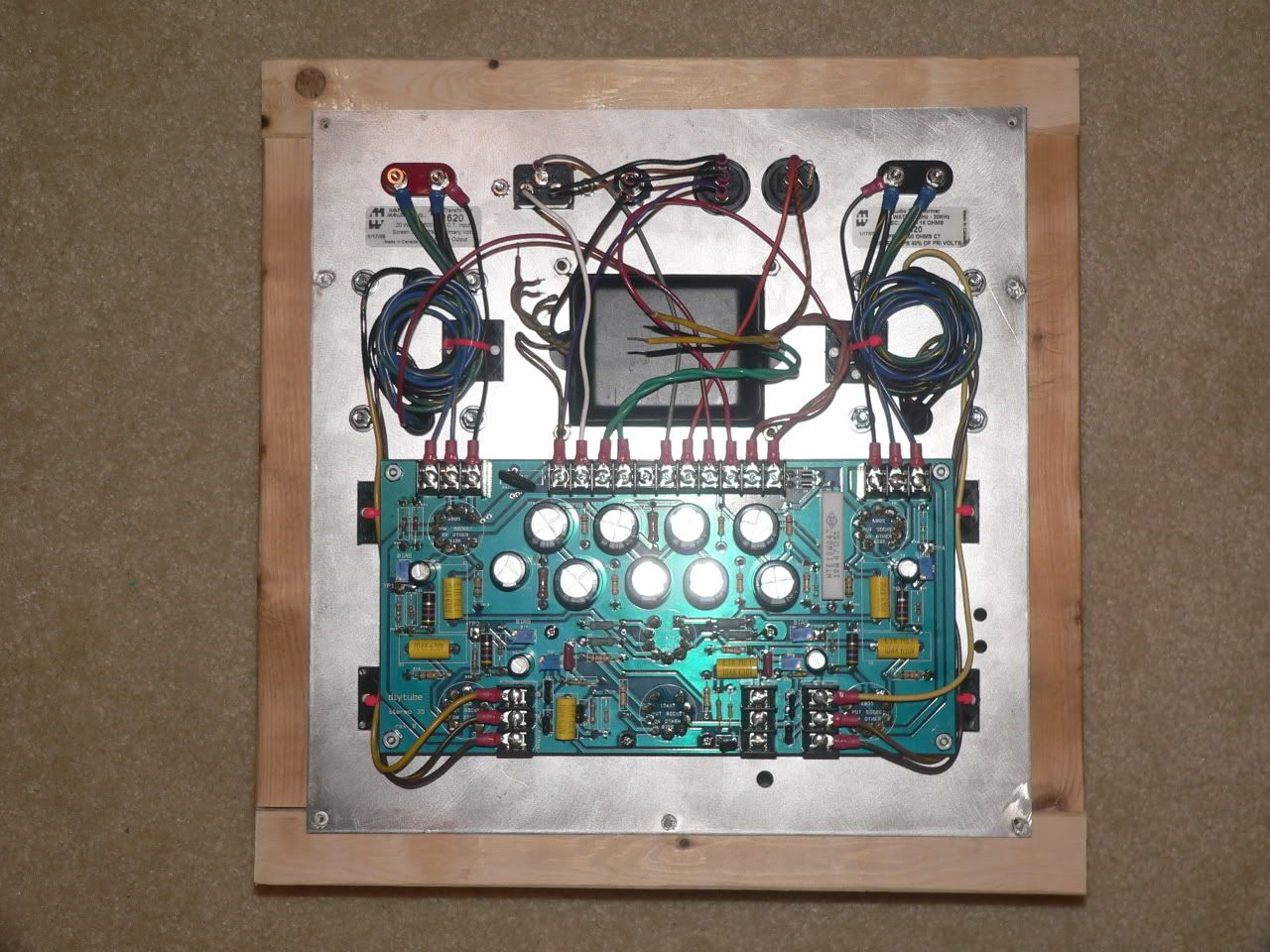
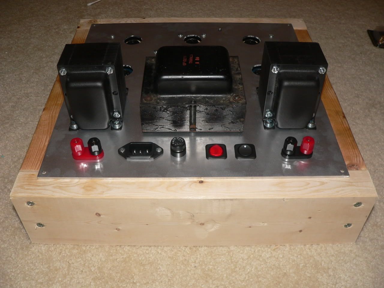
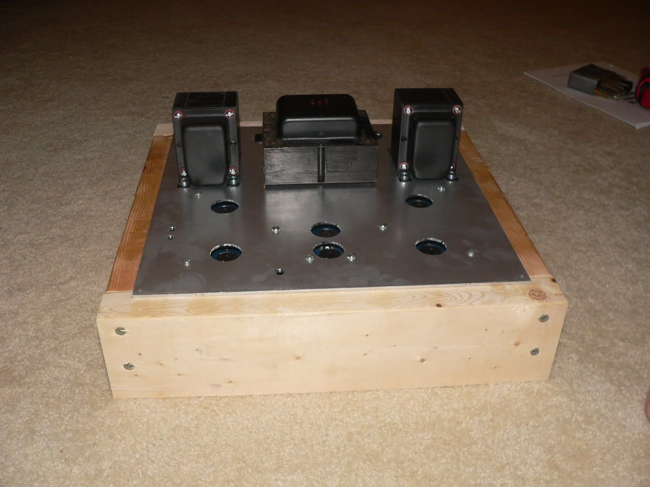
Now I need to use the dremel tool to cutout a hole for the power transformer. It needs to drop down into the chassis, like a Dynaco ST70. Before I cut, which way do I want to orient the transformer? I'd like to minimize the potential for hum. I've picked the way that will make the wiring hookup easiest, but I'm not sure this is the "right" way to minimize hum.

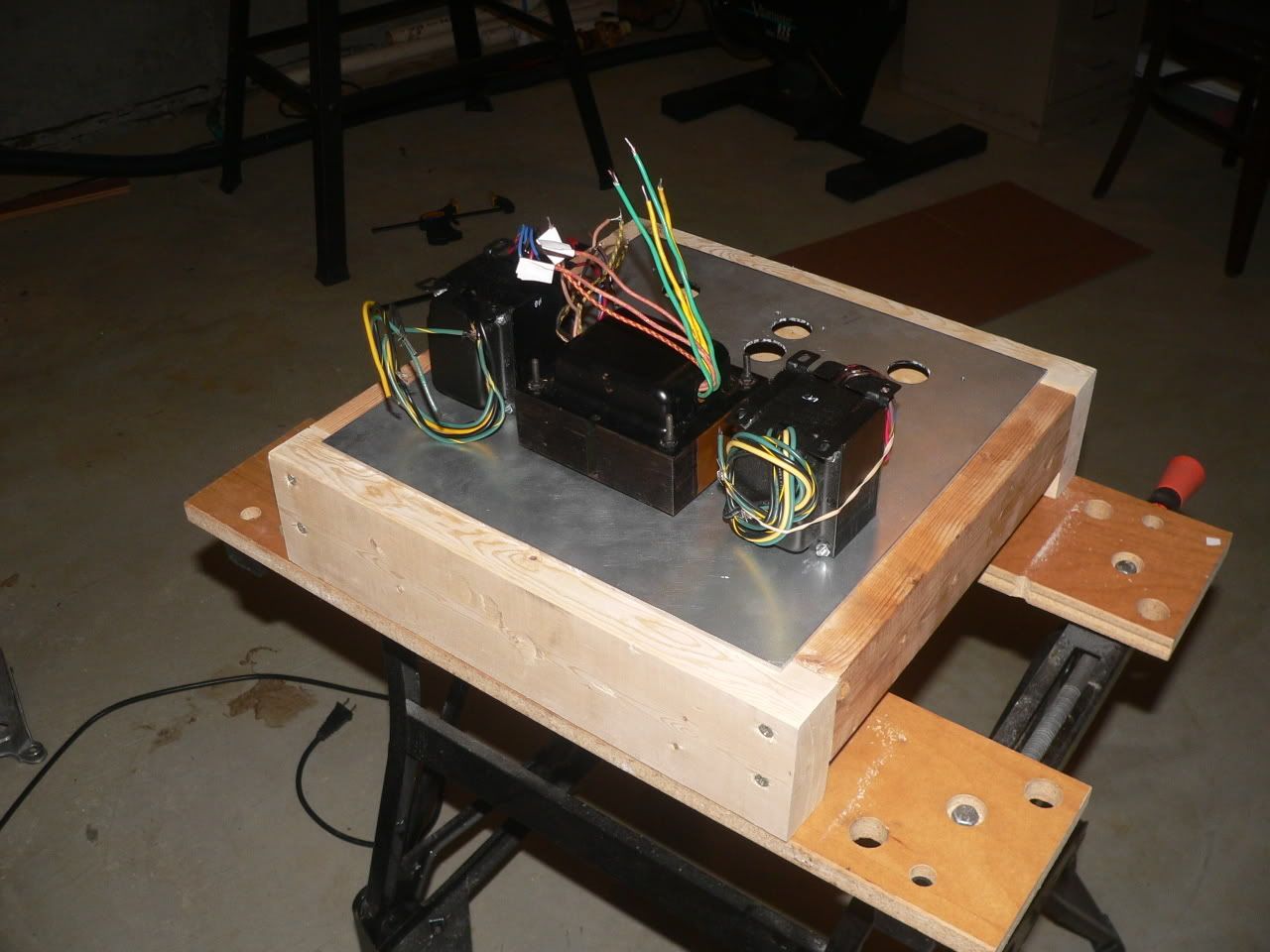
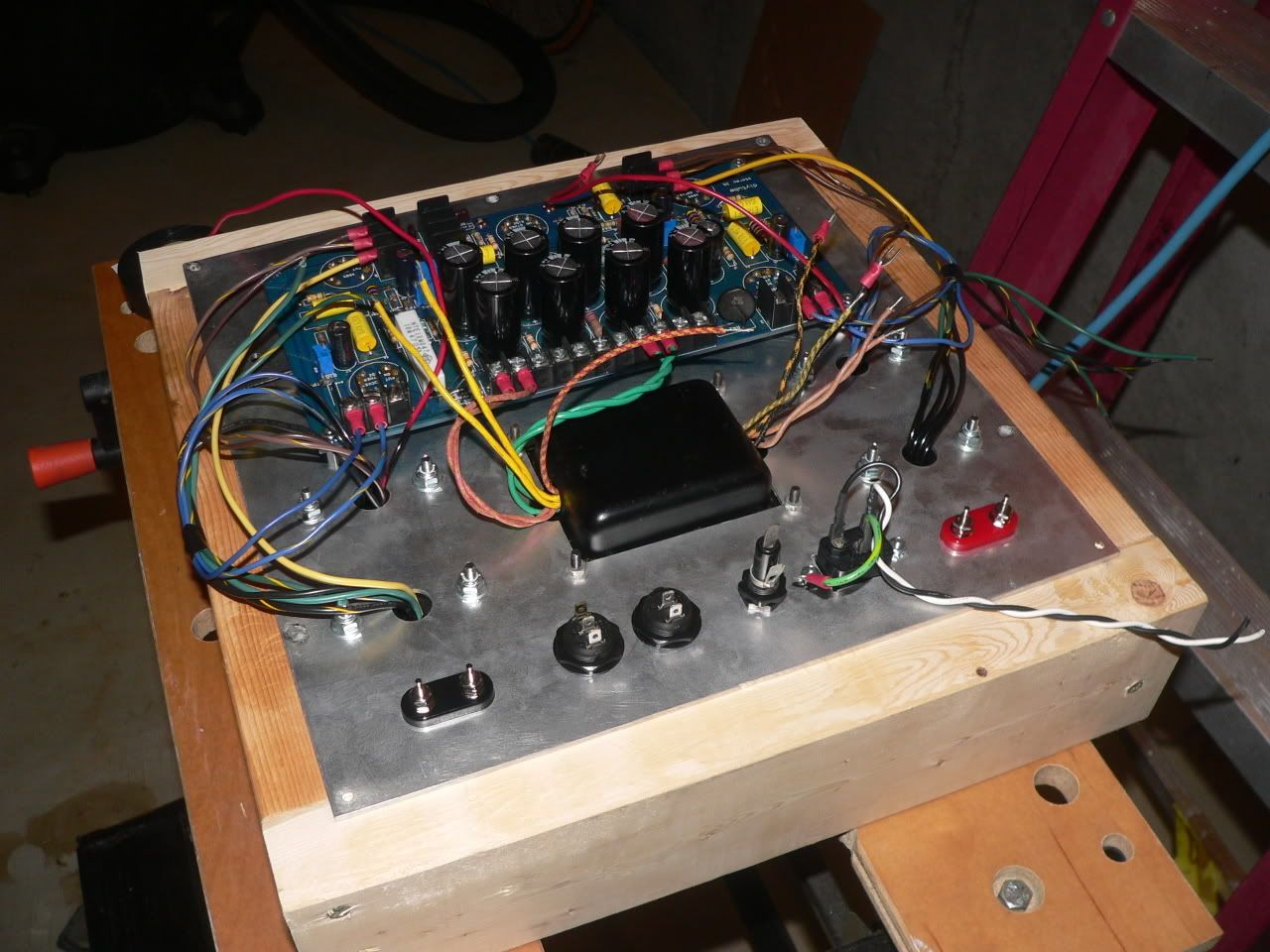
Here's my pictures. All the transformers are sitting on the plate upside down. The don't sit very well right side up, since their wires get in the way without any holes in the plate.

Image Image Image
Last edited by Ty_Bower on Sat Jul 07, 2007 10:18 pm, edited 1 time in total.
User avatar
Ty_Bower
KT88
 
Posts: 1494
Joined: Wed Mar 21, 2007 2:50 pm
Location: Newark, DE

Postby mesherm » Sun Jul 01, 2007 4:33 pm

The orientation in your pic will work fine. I usually mount the power tranny with the primary closest to the on/off switch and the output trannies with the speaker leads closest to the speaker jacks.
User avatar
mesherm
KT88
 
Posts: 1232
Joined: Fri Aug 27, 2004 10:33 pm
Location: Alvin Texas

Postby Ty_Bower » Sun Jul 01, 2007 5:17 pm

I think my other easy option is to turn each OPT ninety degrees, if that makes anything better. Their leads are plenty long, and I should have enough room up top. That also seems to be a pretty common arrangement, looking at other's pictures. Although I haven't yet seen a ST-35 with a thru-mount power tranny...
User avatar
Ty_Bower
KT88
 
Posts: 1494
Joined: Wed Mar 21, 2007 2:50 pm
Location: Newark, DE

Postby erichayes » Sun Jul 01, 2007 7:26 pm

That'll actually make things a little worse, Ty. The way you have them now is as close to ideal as you can get. Remember also that you're dealing with inverse-square stuff here, so the further apart you can get the transformers, the better off you'll be.
Eric in the Jefferson State
erichayes
KT88
 
Posts: 987
Joined: Fri Jan 23, 2004 9:01 pm
Location: McKinleyville CA

Postby Ty_Bower » Mon Jul 02, 2007 2:37 pm

Any harm if I leave the OPTs as shown in the picture, but turn the PT ninety degrees? If I do that, it looks exactly like the layout on a ST70.

It also looks a lot like the layout in this post:
http://diytube.com/phpBB2/viewtopic.php?t=120&start=18

By the way, won't I need some kind of "keyhole" cutouts in the sides of my rectangular PT opening? I don't think the leads will fit through without them.
User avatar
Ty_Bower
KT88
 
Posts: 1494
Joined: Wed Mar 21, 2007 2:50 pm
Location: Newark, DE

Postby mesherm » Mon Jul 02, 2007 3:01 pm

By the way, won't I need some kind of "keyhole" cutouts in the sides of my rectangular PT opening? I don't think the leads will fit through without them.


Here is what you do after you have cut the square hole for the PT.
Remove the bottom bell (the one with holes for the wires) allowing the wires to slide through the holes.
Insert the bottom bell through the square hole.
Now with the bottom bell still in the chassis, feed the wires back through the original holes and reinstall the tranny screws and hardware. Presto!
User avatar
mesherm
KT88
 
Posts: 1232
Joined: Fri Aug 27, 2004 10:33 pm
Location: Alvin Texas

Postby Ty_Bower » Wed Jul 04, 2007 11:59 am

Happy Fourth of July!

No work today, so I made some more progress on the chassis. My woodworking skills are about as good as my metal working skills, so please keep your expectations low. A fifteen inch piece of scrap 2x4 makes the front and the back of the box. Scrap 2x3 makes the sides, giving a nice "handle" for picking it up.

After what felt like a dozen broken Dremel discs, I finally managed to cut out the rectangle for the PT. This aluminum plate is a full 1/8" thick. Next I need to drill the holes for the OPT and the binding posts. I haven't yet decided where to place the input jacks, power switch, and line cord.

With the box frame and the PT nearly in place, I'm starting to get a feel for how my layout is going to work. Here's today's pictures, along with photos of some of the tools I've used...

Image Image Image Image
User avatar
Ty_Bower
KT88
 
Posts: 1494
Joined: Wed Mar 21, 2007 2:50 pm
Location: Newark, DE

Postby TomMcNally » Wed Jul 04, 2007 4:57 pm

Nice progress Ty !

Forget about the lousy Dremel brand cutoff discs ...

look for Gyros brand - http://www.gyrostools.com

# 11-32156 and grab their mandrel model # 80-1800

I use the Dremel tool mostly for cutting IEC Power connector holes in
Hammond steel chassis, and the Gyros last forever, and I've never
had one shatter like the Dremel brand.

Ace Hardware has them, and I have two extra packs, because
they last forever.
User avatar
TomMcNally
Darling du Jour
 
Posts: 2729
Joined: Sat Nov 19, 2005 2:19 pm
Location: Northfield, NJ

Postby Ty_Bower » Wed Jul 04, 2007 7:47 pm

Thanks for the words of encouragement. The transformer holes are all done, and they seem to dry fit just fine. So does the DIY board. I thought a 13x13 would be a lot of space, but it gets used up in a hurry. I'm also trying to mount everything on the top plate, so I've got no side aprons to use. I might have to bend this rule a little, though. Maybe next time I'd do better if I planned the entire layout before I started drilling.

I'll use the space behind the PT for an IEC connector, fuse holder, and power switch. I'm still struggling with where to mount the input jacks. I also have a small 100k Alps stereo volume pot (RS 271-1732) that I'd like to put in as well. There's an inch of free space along the front edge... maybe they can go there.

Image Image Image Image
User avatar
Ty_Bower
KT88
 
Posts: 1494
Joined: Wed Mar 21, 2007 2:50 pm
Location: Newark, DE

Postby Sal Brisindi » Thu Jul 05, 2007 12:32 pm

Ty,
I see one problem, your basement it way to clean.... Yellow_Light_Colorz_PDT_03

Nice job,
Sal
User avatar
Sal Brisindi
KT88
 
Posts: 374
Joined: Thu Mar 22, 2007 5:21 am
Location: Freehold N.J.

Postby Ty_Bower » Fri Jul 06, 2007 11:00 pm

Time to go to bed now... maybe do some more tomorrow.

Do I cut the extra leads on the transformers, or just try to dress them neatly? I need to go to the hardware store and get some blue ring terminals. All mine are red, and they don't fit the Hammonds well. I also need a pair of RCA jacks from the 'Shack.

Image Image Image
User avatar
Ty_Bower
KT88
 
Posts: 1494
Joined: Wed Mar 21, 2007 2:50 pm
Location: Newark, DE

Postby TerrySmith » Sat Jul 07, 2007 7:46 am

What I do with the terminals is pull the blue sleeve off, slide shrink wrap on the wire, fold the wire double and crimp on the terminal and solder it. Then shrink the wrap on it for a professional look.

The reason I like to solder terminals is most are low quality, as are the crimping tools! :o
T. Smith
User avatar
TerrySmith
KT88
 
Posts: 973
Joined: Sat Jan 31, 2004 12:51 pm
Location: Maryville TN

Postby Ty_Bower » Sat Jul 07, 2007 10:42 pm

Most of the wiring is complete, except the input jacks and volume pot. I'm not completely sure I'm happy with the way the wiring is dressed. I don't like the coils of extra wire around the outputs. I think I might need to go back and cut off the excess leads on the Hammonds. I also have a few unused leads on the Allied PT (5v heater, center tap for 6.3v, and 20v bias tap). Something needs to be done with them. I've run a couple leads really close to the edge of the DIY board. I seem to recall the AC for the heaters lives there, and it's best to keep any wiring away.

On the plus side, I can pick up the plate, and flip it over either way and it will sit neatly on the wooden frame. Everything is contained on the plate. I just need to find the right size wood screws to attach the plate to the frame. Random fact - my DIY ST-35 currenty weighs 22.4 pounds (without tubes).

I wish I had cut the hole for the IEC ninety degrees from where it is now. Then I could get one of those right angle power cords, and I wouldn't have the cord sticking up.

I went ahead and installed the standby switch, along with a 1 meg resistor across it. Hopefully I won't have any problems there.

This is a Rev B board, and the standoffs are non-insulated. I went ahead and connected the ground lead of the IEC to the DIY board per the manual. If I hear any humming, it'll be the first to get disconnected.

All the wiring around the IEC, fuse, and switches are quick-disconnect. I could probably take the whole thing apart within ten minutes if I wanted. The only thing that might slow me down is the cable ties holding the coils of extra transformer leads.

If it isn't obvious, in the first picture the chassis plate is just flipped over on the wooden frame. It makes for real easy access to all the parts, as there are no sides to get in the way.

Image Image Image Image
User avatar
Ty_Bower
KT88
 
Posts: 1494
Joined: Wed Mar 21, 2007 2:50 pm
Location: Newark, DE

Postby Ty_Bower » Sun Jul 08, 2007 10:10 pm

It works. Sounds great. There's a slight mechanical hum from the PT, but zero hum from the speakers. This power transformer must be quite a bit larger than what the ST-35 needs, as it hardly gets warm to the touch. Overall, the amp has plenty of power and a nice clean sound.

Image Image
User avatar
Ty_Bower
KT88
 
Posts: 1494
Joined: Wed Mar 21, 2007 2:50 pm
Location: Newark, DE

Postby jduffy » Mon Jul 09, 2007 1:14 am

Excellent night shot!

Nice job on the amplifier. You must be pretty psyched. :)
User avatar
jduffy
 
Posts: 43
Joined: Sat Jan 06, 2007 2:52 pm
Location: SoCal

Next

Return to stereo 35

Who is online

Users browsing this forum: No registered users and 28 guests

cron