Getting to know Shannon has been one of the highlights of my past year. His enthusiasm and hard work is revolutionizing the DIY tube industry. These diytube circuit boards are amazing. High quality and well laid out. So when he offered me the chance to be one of the first to build an amp with his Rev C board, I jumped at the chance. :multi:
I built a ST35 clone using Dynaco SCA35 transformers several years ago. It is mostly point-to-point wiring with a couple of home-etched circuit boards. I used fairly high quality components in the construction and put it into a Hammond steel 12x8x2 chassis. Looks very much like Shannon’s. Anyway, I have never been real thrilled with the sound of this amp. Probably because I have 4-ohm speakers and only an 8-ohm tap on the Dyna trannies. So this old amp became a basement work bench amp connected to cheap KLH speakers and an old Dyna tuner.
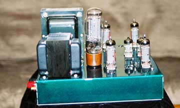
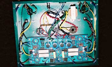
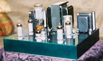
So I wanted my first diytube project to be a GREAT sounding amp. To accomplish this, I adopted the following design criteria. First, I wanted to use tube rectification. Because tube rectifiers look and sound soooo good. (I can see Shannon rolling his eyes) Second, I wanted to use only very high quality parts, especially in the signal path. Third, I only used soldered connections inside the amp. Fourth, I would use current production, quality output and power transformers operated very conservatively. I want to push the tubes, not the iron. Last, the amp would have to look like a high quality commercial amplifier.
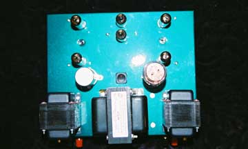
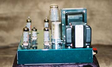
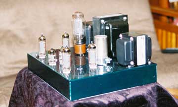
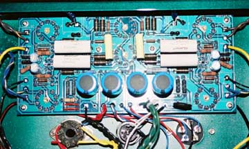
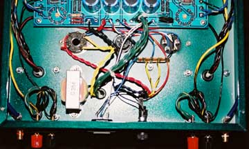
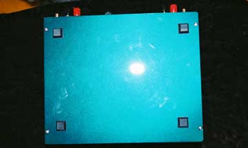
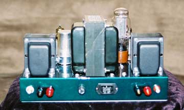
Parts Selection: I chose Hammond Iron, 1650F for the outputs and a 272JX for the power. The chassis was Hammond steel 12x10x2 with bottom plate. After cutting and drilling all the holes, I had the chassis and bottom plate painted metallic emerald green at the local body shop. For my coupling caps I purchased matched pairs of Multicap RTX polystyrene and tin foil. Plate load resistors were 3-watt IRC metal films. All signal path resistors were 1/2 or 3-watt IRC, but I used some Vishay in the feedback circuits. The .22 uf cap in the positive feedback was an AudioCap. Speaker and RCA jacks were gold plated Vampire. All internal hookup wire was Kimber TCSS except the input which used Cardas 2x21 shielded cable. The PC mount tube sockets were the Japanese gold plated ones sold by Angela. (very high quality, but $6 apiece) The rectifier socket was NOS Cinch and the filter choke was new Dyna replacement sold by Triode Electronics. I did not use any screw mount terminal strips in this construction. I also did not use a pot in the negative feedback, but chose a fixed value Vishay instead.
The power supply had to be changed to accommodate the tube rectifier. I copied the Dyna ST70 Pi type arrangement. I used the 40 uf section of a quad section LCR cap for the input and took the other side of the choke to PCB. I jumpered the spot on the board for the diodes, and used the recommended 120 uf power supply caps. The only other mod to the power supply was that I combined the 2nd and 3rd stages with a jumper and used a 6.8 kohm dropping resistor between the 3rd and 4th stages. I also combined the other three 20 uf section of the quad cap to give me a total of 300uf on the B+.
I finished soldering on Sunday and put in some tubes (JJ EL84’s, JJ 5AR4, and German 12AU7/12AX7). The unit powered up the first time with no troubleshooting. The power tubes biased right up and stabilized. At first the B+ was a little high at 388 volts, but then I replaced the JJ 5AR4 with a Mullard CV378 rectifier and the B+ was reduced to about 357 volts. Perfect!! I then took the amp upstairs to get my first listening impressions. Except for a mysterious hum problem (fixed by swapping patch cords), the amp sounded wonderful. Much to my wife’s dismay, I stayed up late rediscovering a bunch of cherished recordings. :agrue:
Overall, this amp sounds very, very good. Detailed, dynamic, and very pleasant to listen to. Not fatiguing. The low bass foundation is not there but the bass is tight and detailed. The amp doesn’t seem to have any trouble interfacing with the Apogees. This amp will stay put in my main system for a while, at least until I build a pair of Ikes. I have 4 quads of EL84s that I want to compare. Pictures of the amp to follow.
JT
Rev C Completed
4 posts
• Page 1 of 1
Rev C Completed
![]() by Thermion » Wed Jan 14, 2004 9:28 pm
by Thermion » Wed Jan 14, 2004 9:28 pm
- Thermion
- Posts: 181
- Joined: Mon Jul 07, 2003 6:04 pm
- Location: Fisher, IL
pictures are here!
![]() by Shannon Parks » Fri Jan 23, 2004 9:07 pm
by Shannon Parks » Fri Jan 23, 2004 9:07 pm
Just got these in the mail from Thermion!
Shannon
Shannon
-

Shannon Parks - Site Admin
- Posts: 3764
- Joined: Tue Mar 18, 2003 5:40 pm
- Location: Poulsbo, Washington
JT's Rev C Performance
![]() by Thermion » Fri Jan 23, 2004 10:05 pm
by Thermion » Fri Jan 23, 2004 10:05 pm
Last week I had the chance to measure the performance of my Rev C amp. In the first series, I had the 18pf screen cap feedback capacitor installed, and then I clipped it out of the circuit for the other tests. The trade off is better high frequency bandwith but also higher distortion. Anyway, here is the data:
400mv input before snipped screen caps:
20Hz 3.64V +19.1dB .356%THD+N 3.258W @ 4ohm
25Hz 3.6V +19.0dB .1642%THD+N 3.24W @ 4ohm
30Hz 3.6V +19.0dB .1173%THD+N 3.24W @ 4ohm
50Hz 3.6V +19.0dB .0716%THD+N 3.24W @ 4ohm
100Hz 3.6V +19.0dB .0563%THD+N 3.24W @ 4ohm
200Hz 3.61V +19.0dB .0511%THD+N 3.24W @ 4ohm
500Hz 3.6V +19.0dB .0431%THD+N 3.24W @ 4ohm
1kHz 3.61V +19.0dB .0459%THD+N 3.24W @ 4ohm
2kHz 3.6V +19.0dB .082%THD+N 3.222W @ 4ohm
5kHz 3.58V +18.9dB .2002%THD+N 3.186W @ 4ohm
10kHz 3.46V +18.6dB .368%THD+N 2.976W @ 4ohm
20kHz 3.07V +17.5dB .5%THD+N 2.341W @ 4ohm
30kHz 2.536V +15.9dB 1.403%THD+N 1.608W @ 4ohm
40kHz 1.907V +13.5dB 4.2%THD+N .9092W @ 4ohm
50kHz 1.646V +12.2dB 5.78%THD+N .6773W @ 4ohm
60kHz 1.413V +10.9dB 4.08%THD+N .4991W @ 4ohm
70kHz 1.073V +8.6dB 2.471%THD+N .2873W @ 4ohm
80kHz .827V +6.4dB 1.788%THD+N .171W @ 4ohm
90kHz .796V +6.1dB 1.564%THD+N .1584W @ 4ohm
10k0Hz .856V +6.7dB 1.45%THD+N .1832W @ 4ohm
400mv after snipped screen caps:
20Hz 3.62V +19.0dB .37%THD+N 3.276W @ 4ohm
25Hz 3.61V +19.0dB .1643%THD+N 3.258W @ 4ohm
30Hz 3.61V +19.0dB .1131%THD+N 3.24W @ 4ohm
50Hz 3.61V +19.0dB .0698%THD+N 3.24W @ 4ohm
100Hz 3.61V +19.0dB .0552%THD+N 3.258W @ 4ohm
200Hz 3.61V +19.0dB .0513%THD+N 3.258W @ 4ohm
500Hz 3.61V +19.0dB .048%THD+N 3.258W @ 4ohm
1kHz 3.61V +19.0dB .0554%THD+N 3.258W @ 4ohm
2kHz 3.61V +19.0dB .1038%THD+N 3.24W @ 4ohm
5kHz 3.61V +19.0dB .2693%THD+N 3.24W @ 4ohm
10kHz 3.57V +18.8dB .567%THD+N 3.168W @ 4ohm
20kHz 3.41V +18.4dB 1.02%THD+N 2.89W @ 4ohm
30kHz 3.16V +17.8dB 2.832%THD+N 2.465W @ 4ohm
40kHz 2.516V +15.9dB 6.21%THD+N 1.583W @ 4ohm
50kHz 2.305V +15.2dB 8.27%THD+N 1.327W @ 4ohm
60kHz 2.193V +14.8dB 6.43%THD+N 1.202W @ 4ohm
70kHz 1.857V +13.4dB 3.92%THD+N .864W @ 4ohm
80kHz 1.598V +12.1dB 2.968%THD+N .6392W @ 4ohm
90kHz 1.536V +11.8dB 1.937%THD+N .5891W @ 4ohm
10k0Hz 1.514V +11.6dB 1.958%THD+N .5753W @ 4ohm
700mv input after snipped screens:
20Hz 6.16V +18.8dB 4.12%THD+N 9.517W @ 4ohm
25Hz 6.24V +18.9dB 1.426%THD+N 9.766W @ 4ohm
30Hz 6.25V +18.9dB 1.237%THD+N 9.828W @ 4ohm
50Hz 6.27V +19.0dB .751%THD+N 9.766W @ 4ohm
100Hz 6.27V +19.0dB .306%THD+N 9.797W @ 4ohm
200Hz 6.27V +19.0dB .1631%THD+N 9.797W @ 4ohm
500Hz 6.26V +18.9dB .1173%THD+N 9.828W @ 4ohm
1kHz 6.27V +19.0dB .1208%THD+N 9.797W @ 4ohm
2kHz 6.28V +19.0dB .1919%THD+N 9.828W @ 4ohm
5kHz 6.26V +18.9dB .473%THD+N 9.766W @ 4ohm
10kHz 6.2V +18.7dB .975%THD+N 9.61W @ 4ohm
20kHz 5.92V +18.0dB 1.784%THD+N 8.762W @ 4ohm
30kHz 5.49V +17.1dB 6.64%THD+N 7.508W @ 4ohm
40kHz 4.43V +14.9dB 11.33%THD+N 4.862W @ 4ohm
50kHz 4.03V +13.7dB 15.87%THD+N 4.04W @ 4ohm
60kHz 3.69V +12.6dB 12.19%THD+N 3.386W @ 4ohm
70kHz 3.05V +10.6dB 6.83%THD+N 2.326W @ 4ohm
80kHz 2.595V +8.9dB 4.85%THD+N 1.706W @ 4ohm
90kHz 2.507V +8.3dB 2.923%THD+N 1.57W @ 4ohm
10k0Hz 2.46V +7.9dB 3.1%THD+N 1.541W @ 4ohm
890mv input after snipped screen caps:
20Hz 6.94V +17.7dB 12.1%THD+N 11.9W @ 4ohm
25Hz 7.34V +18.2dB 4.5%THD+N 13.51W @ 4ohm
30Hz 7.51V +18.4dB 2.607%THD+N 14.18W @ 4ohm
50Hz 7.63V +18.6dB 1.356%THD+N 14.55W @ 4ohm
100Hz 7.66V +18.6dB 1.084%THD+N 14.63W @ 4ohm
200Hz 7.68V +18.6dB .948%THD+N 14.71W @ 4ohm
500Hz 7.7V +18.6dB .905%THD+N 14.78W @ 4ohm
1kHz 7.69V +18.6dB .894%THD+N 14.78W @ 4ohm
2kHz 7.7V +18.6dB 1.055%THD+N 14.82W @ 4ohm
5kHz 7.69V +18.5dB 1.783%THD+N 14.75W @ 4ohm
10kHz 7.6V +18.3dB 2.874%THD+N 14.4W @ 4ohm
20kHz 7.3V +17.8dB 4.49%THD+N 13.29W @ 4ohm
30kHz 6.71V +16.7dB 10.12%THD+N 11.26W @ 4ohm
40kHz 5.44V +14.6dB 17.31%THD+N 7.371W @ 4ohm
50kHz 4.97V +13.4dB 23.17%THD+N 6.15W @ 4ohm
60kHz 4.38V +12.0dB 15.01%THD+N 4.774W @ 4ohm
70kHz 3.55V +9.8dB 8.7%THD+N 3.133W @ 4ohm
80kHz 2.983V +8.0dB 6.31%THD+N 2.22W @ 4ohm
90kHz 2.762V +7.0dB 4.06%THD+N 1.917W @ 4ohm
10k0Hz 2.64V +6.4dB 4.67%THD+N 1.744W @ 4ohm
The distortion at 3 watts is amazing for a tube amp. However, the peformance at 14 watts is really beyond the envelop. I was using a Telefunkin 12AX7 abd 12AU7 at the input, Mullard CV378 rectifier, and NOS Phillips Miniwatt tubes (Australian) on the output. Wish that I had used a quad of JJ or EI EL84s for the output.
JT
- Thermion
- Posts: 181
- Joined: Mon Jul 07, 2003 6:04 pm
- Location: Fisher, IL
Excellent!
![]() by EWBrown » Mon Jan 26, 2004 6:54 am
by EWBrown » Mon Jan 26, 2004 6:54 am
Looks like a really nice DIY job there!
I am almost completed with the second Rev C, just need four binding posts and it's done. (They are on the way from AES as of last wednesday).
This was built onto a Hammond 12X8X2 steel (painted gray) chassis, with the bottom plate and the cage top. OPTs are Hammond 1620s, PT is the "Uncle Ned" PA-774 replacement. the four EL84 grid caps are Auricap 0.1 / 450 V, the 4 cathode resistors are 510 ohm, and since I'm using 8 ohms as the feedback point, the two NFB pots are 50K, instead of 100K, preset to 19.2 K to ground as described elsewhere. Everything else is pretty much by the book.
BTW, the 1620s are a tad "fatter" than the 1650Fs or HWT 25W OPTs. The core stacks are about 1/4 inch thicker, but I still had plenty of room.
One method to get those tube sockets centered just right, especially if you use 7/8" or 1" dia holes, is to install the sockets, without soldering, then mount the board, make sure the sockets are centered properly, and then solder them in. There is a bit of "wiggle room" available, so any minor metal working errors can easily be compensated.
/ed brown in NH
Real Radios Glow in the Dark
-

EWBrown - Insulator & Iron Magnate
- Posts: 6389
- Joined: Wed Mar 19, 2003 6:03 am
- Location: Now located in Clay County, NC !
4 posts
• Page 1 of 1
Who is online
Users browsing this forum: No registered users and 46 guests